xcore.ai Ethernet Development Kit
The xcore.ai Ethernet Development Kit (XK-ETH-316-DUAL) is an development board for the xcore.ai multi-core microcontroller from XMOS.
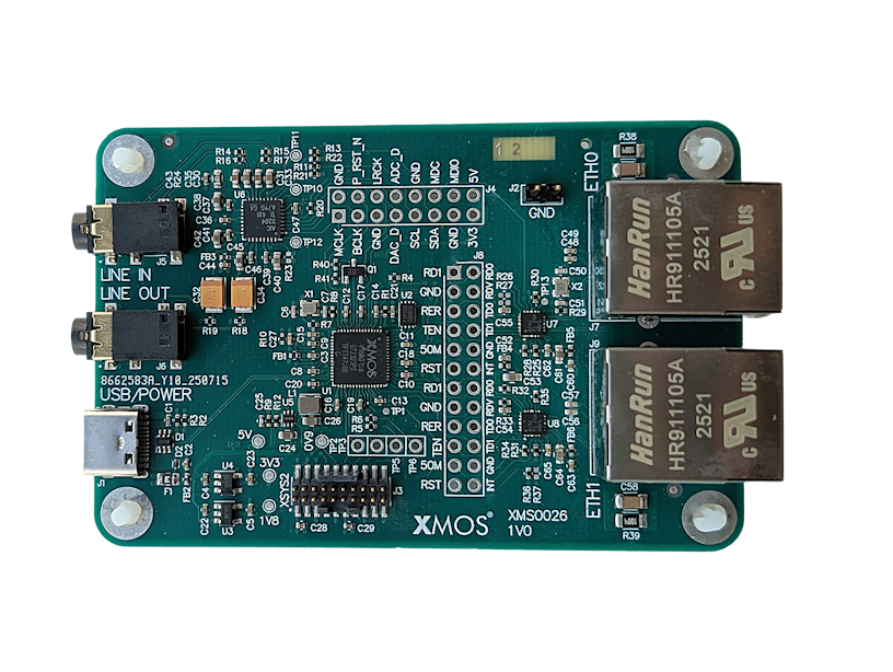
Fig. 4 xcore.ai Ethernet Development Kit
The XK-ETH-316-DUAL allows testing in multiple application scenarios and provides a good general software development board for simple tests and demos. The XK-ETH-316-DUAL comprises an xcore.ai processor with a set of I/O devices and connectors arranged around it, as shown in Fig. 5.

Fig. 5 xcore.ai Ethernet Development Kit block diagram
External hardware features board include, audio codec with line-in and line-out jack, QSPI flash memory and a USB-C connector for power and data.
The kit also contains an XTAG debug adapter and is fully supported by the XTC Tools development environment.
For full details regarding the hardware please refer to XK-ETH-316-DUAL xcore.ai Ethernet Development Kit.
Warning
The xcore.ai Ethernet Development Kit is a general purpose evaluation platform and should be considered an “example” rather than a fully fledged reference design.
Hardware Features
The location of the various features of the xcore.ai Ethernet Development Board is shown in Fig. 6.
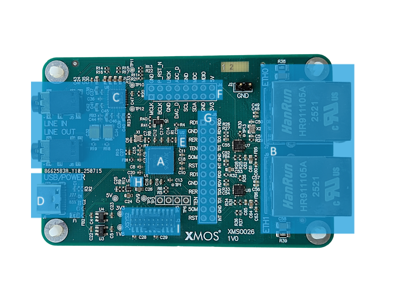
Fig. 6 xcore.ai Ethernet Development Kit hardware features
It includes the following features:
A: xcore.ai (XU316-1024-QF60B-C24) device
B: Dual 100 Base-T Ethernet ports
C: Audio codec with line-in and line-out jacks
D: USB-C jack
E: Quad-SPI flash memory
F: Audio signal breakout header 2.54mm (0.1”)
G: Ethernet signal breakout header 2.54mm (0.1”)
H: 25 MHz Crystal
I: XTAG4 debugger connector
Analogue Audio Input & Output
A stereo CODEC (TLV320AIC3204), connected to the xcore.ai device via an I²S interface, provides analogue input/output functionality at line level.
The audio CODEC is configured by the xcore.ai device via an I²C bus.
Audio Clocking
xcore.ai devices are equipped with a secondary (or application) PLL which is used to generate the audio clocks for the CODEC.
Power
The XK-ETH-316-DUAL requires a 5V power source that is normally provided through the USB-C cable J1. The voltage is converted by on-board regulators to the 0V9, 1V8 and 3V3 supplies used by the components.
The board should therefore be configured to present itself as a bus powered device when connected to an active USB host.
Debug
For convenience the kit includes an xTAG4 for debugging via JTAG/xSCOPE. The debugger connects via ribbon connector J3 (marked XSYS2). The debugger is accessed via the USB (micro-B) receptacle of the xTAG.