xcore.ai Multi-Channel Audio Board
The XMOS xcore.ai Multichannel Audio Board (XK-AUDIO-316-MC) is a complete hardware and software reference platform targeted at up to 32-channel USB audio applications, such as DJ decks, mixers and other musical instrument interfaces. The board can also be used to prototype products with reduced feature sets or HiFi style products.
The XK-AUDIO-316-MC is based around the XU316-1024-TQ128-C24 multicore microcontroller; a dual-tile xcore.ai device with an integrated High Speed USB 2.0 PHY and 16 logical cores delivering up to 2400MIPS of deterministic and responsive processing power.
Exploiting the flexible programmability of the xcore.ai architecture, the XK-AUDIO-316-MC supports a USB audio source, streaming 8 analogue input and 8 analogue output audio channels simultaneously - at up to 192kHz. It also supports digital input/output streams (S/PDIF and ADAT) and MIDI. Ideal for consumer and professional USB audio interfaces. The board can also be used for testing general purpose audio DSP activities - mixing, filtering, etc.
For full details regarding the hardware please refer to xcore.ai Multichannel Audio Platform Hardware Manual.
Hardware Features
The location of the various features of the xcore.ai Multichannel Audio Board (XK-AUDIO-316-MC) is shown in Fig. 1.
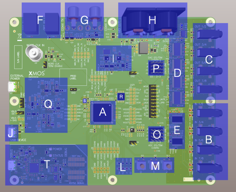
Fig. 1 xcore.ai Multichannel Audio Board hardware features
It includes the following features:
A: xcore.ai (XU316-1024-TQ128-C24) device
B: 8 line level analog inputs (3.5mm stereo jacks)
C: 8 line level analog outputs (3.5mm stereo jacks)
D: 384kHz 24 bit audio DACs
E: 192kHz 24 bit audio ADCs
F: Optical connections for digital interface (e.g. S/PDIF and ADAT)
G: Coaxial connections for digital interfaces (e.g. S/PDIF)
H: MIDI in and out connections
I: Flexible audio master clock generation
J: USB 2.0 micro-B jacks
L: 4 general purpose LEDs
M: 3 general purpose buttons
O: Flexible I²S/TDM input data routing
P: Flexible I²S/TDM output data routing
Q: Integrated power supply
R: Quad-SPI boot ROM
S: 24MHz Crystal
T: Integrated XTAG4 debugger
Analogue Input & Output
A total of eight single-ended analog input channels are provided via 3.5mm stereo jacks. These inputs feed into a pair of quad-channel PCM1865 ADCs from Texas Instruments.
A total of eight single-ended analog output channels are provided. These are fed from four PCM5122 stereo DAC’s from Texas instruments.
All ADC’s and DAC’s are configured via an I²C bus. Due to an clash of device addresses a I²C multiplexor is used.
The four digital I²S/TDM input and output channels are mapped to the xCORE input/outputs through a header array. These jumpers allow channel selection when the ADCs/DACs are used in TDM mode.
Digital Input & Output
Optical and coaxial digital audio transmitters are used to provide digital audio input output in formats such as IEC60958 consumer mode (S/PDIF) and ADAT. The output data streams from the xcore are re-clocked using the external master clock to synchronise the data into the audio clock domain. This is achieved using simple external D-type flip-flops.
MIDI
MIDI input and output is provided on the board via standard 5-pin DIN connectors compliant to the MIDI specification. The signals are buffered using 5V line drivers and are then connected ports on the xCORE, via a 5V to 3.3V buffer. A 1-bit port is used for receive and a 4-bit port is used for transmit. A pull-up resistor on the MIDI output ensures there is no MIDI output when the xcore device is not actively driving the output.
Audio Clocking
In order to accommodate a multitude of clocking options a flexible clocking scheme is provided for the audio subsystem.
Three methods of generating an audio master clock are provided on the board:
A Cirrus Logic CS2100-CP PLL device. The CS2100 features both a clock generator and clock multiplier/jitter reduced clock frequency synthesizer (clean up) and can generate a low jitter audio clock based on a synchronisation signal provided by the xcore
A Skyworks Si5351B PLL device. The Si5351 is an I²C configurable clock generator that is suited for replacing crystals, crystal oscillators, VCXOs, phase-locked loops (PLLs), and fanout buffers.
xcore.ai devices are equipped with a secondary (or application) PLL which can be used to generate audio clocks.
Selecting between these methods is done via writing to bits 6 and 7 of PORT 8D on tile[0]. See Control I/O.
Note
lib_board_support currently only supports the xcore.ai secondary PLL and CS2100 device
Control I/O
4 bits of PORT 8C are used to control external hardware on the board. This is described in PORT 8C functionality.
Bit(s) |
Functionality |
0 |
1 |
|---|---|---|---|
[0:3] |
Unused |
||
4 |
Enable 3v3 power for digital (inverted) |
Enabled |
Disabled |
5 |
Enable 3v3 power for analogue |
Disabled |
Enabled |
6 |
PLL Select |
CS2100 |
Si5351B |
7 |
Master clock direction |
Output |
Input |
Note
To use the xcore application PLL bit 7 should be set to 0. To use one of the external PLL’s bit 7 should be set to 1.
Power
The board is capable of acting as a USB2.0 self or bus powered device. If bus powered, the board takes
power from the USB DEVICE connector (micro-B receptacle). If self powered, board takes power
from EXTERNAL POWER input (micro-B receptacle).
A power source select jumper (marked PWR SRC) is used to select between bus and self-powered configuration.
Note
To remain USB compliant the software should be properly configured for bus vs self powered operation
Debug
For convenience the board includes an on-board xTAG4 for debugging via JTAG/xSCOPE.
This is accessed via the USB (micro-B) receptacle marked DEBUG.