xcore.ai Evaluation Kit
The XMOS xcore.ai Evaluation Kit (XK-EVK-XU316) is an evaluation board for the xcore.ai multi-core microcontroller from XMOS.
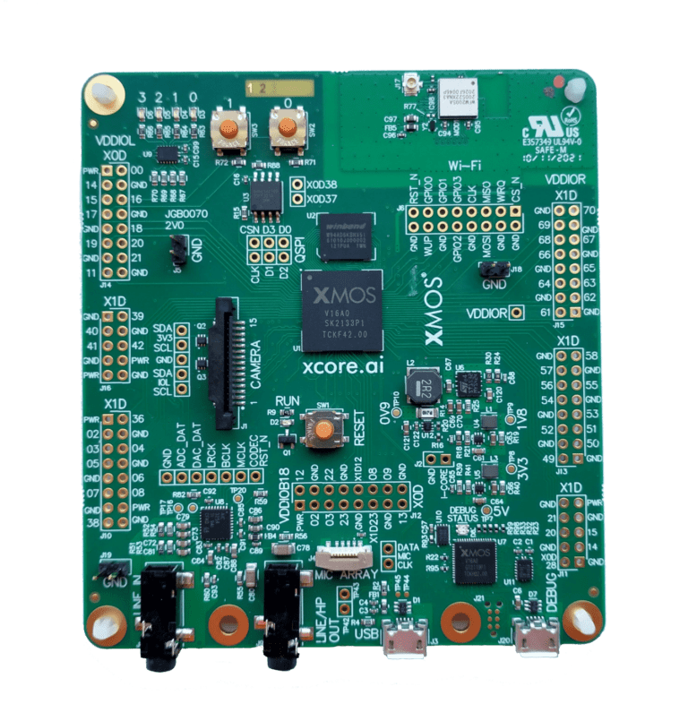
Fig. 2 xcore.ai Evaluation Kit
The XK-EVK-XU316 allows testing in multiple application scenarios and provides a good general software development board for simple tests and demos. The XK-EVK-XU316 comprises an xcore.ai processor with a set of I/O devices and connectors arranged around it, as shown in Fig. 3.
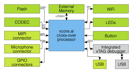
Fig. 3 xcore.ai Evaluation Kit block diagram
External hardware features board include, four general purpose LEDs, two general purpose push-button switches, a PDM microphone connector, audio codec with line-in and line-out jack, QSPI flash memory, LPDDR1 external memory 58 GPIO connections from tile 0 and 1, micro USB for power and host connection, MIPI connector for a MIPI camera, integrated xTAG debug adapter and a reset switch with LED to indicate running.
For full details regarding the hardware please refer to XK-EVK-XU316 xcore.ai Evaluation Kit Manual.
Warning
The xcore.ai Evaluation Kit is a general purpose evaluation platform and should be considered an “example” rather than a fully fledged reference design.
Analogue Audio Input & Output
A stereo CODEC (TLV320AIC3204), connected to the xcore.ai device via an I²S interface, provides analogue input/output functionality at line level.
The audio CODEC is are configured by the xcore.ai device via an I²C bus.
Audio Clocking
xcore.ai devices are equipped with a secondary (or application) PLL which is used to generate the audio clocks for the CODEC.
Power
The XK-EVK-XU316 requires a 5V power source that is normally provided through the micro-USB cable J3. The voltage is converted by on-board regulators to the 0V9, 1V8 and 3V3 supplies used by the components.
The board should therefore be configured to present itself as a bus powered device when connected to an active USB host.
Debug
For convenience the board includes an on-board xTAG4 for debugging via JTAG/xSCOPE.
This is accessed via the USB (micro-B) receptacle marked DEBUG.