lib_spi: SPI library
Introduction
SPI is a four-wire hardware bi-directional serial interface.
This library provides a software defined, industry-standard, SPI (serial peripheral
interface) component that allows you to control an SPI bus via the
xcore GPIO ports.
The SPI bus can be used by multiple tasks within the xcore device
and (each addressing the same or different slaves) and
is compatible with other slave devices on the same bus.
Available SPI components
Three components are provided in this library which offer different functionality. They are all defined as a task with an interface which provides methods for transmitting and receiving data. All components offer a shutdown() method allowing the component to be exited at runtime which frees any resources used.
SPI Master (Synchronous)
This component is the standard SPI master and is simplest to use. The synchronous aspect refers to the API and operation and
means that calls to this component block until the transaction has completed. The component
server may be placed on the same or a different tile from the client. If placed on the same
tile, the task may be distributed by the compiler which means it gets turned into a function
call and consequently does not consume an xcore thread.
Multiple clients are supported and are arbitrated by the component. Multiple devices are also supported by means of individual slave select bits within a port.
SPI Master (Asynchronous)
This component offers buffering functionality over the synchronous SPI master. The asynchronous feature means that calls to this component can be non-blocking and SPI transfers may be queued. The component server may be placed on the same or a different tile from the client.
Due to the buffering logic, the asynchronous version always consumes an xcore thread.
Multiple clients are supported and are arbitrated by the component. Multiple devices are also supported by means of individual slave select bits within a port.
SPI Slave
The SPI slave component task always runs in its own xcore thread because it needs to be
responsive to the external master requests. It offers a single slave device with basic
8 or 32 bit transfer support.
It provides callbacks for when the slave needs data to transmit or has received data, as
well as a callback to indicate the end of a transaction.
SPI Modes
The data sample points for SPI are defined by the clock polarity (CPOL) and clock phase (CPHA) parameters. SPI clock polarity may be inverted or non-inverted by the CPOL and the CPHA parameter is used to shift the sampling phase. The following four sections illustrate the MISO and MOSI data lines relative to the clock. The timings are given by:
Parameter |
Description |
|---|---|
t1 |
The minimum time from the start of the transaction (SS asserted) to the first sample point/active clock edge. |
t2 |
The minimum amount of time from the last sample point/active clock before SS is de-asserted. |
t3 |
The inter-transmission gap. This is the minimum amount of time that the slave select must be de-asserted between accesses on the same device. |
MAX CLOCK RATE |
This is the maximum clock rate supported by the configuration. |
The setup and hold timings are inherited from the underlying xcore
device. For details on these timing please refer to the device datasheet.
When operating above 20 Mbps please also see the MISO port timing section.
Mode 0 - CPOL: 0 CPHA 0

Fig. 1 Mode 0
The master and slave will drive out their first data bit before the first rising edge of the clock then drive on subsequent falling edges. They will sample on rising edges.
Mode 1 - CPOL: 0 CPHA 1

Fig. 2 Mode 1
The master and slave will drive out their first data bit on the first rising edge of the clock and sample on the subsequent falling edge.
Mode 2 - CPOL: 1 CPHA 0

Fig. 3 Mode 2
The master and slave will drive out their first data bit before the first falling edge of the clock then drive on subsequent rising edges. They will sample on falling edges.
Mode 3 - CPOL: 1 CPHA 1

Fig. 4 Mode 3
The master and slave will drive out their first data bit on the first falling edge of the clock and sample on the subsequent rising edge.
External signal description
The SPI protocol requires a clock, one or more slave selects and either one or two data wires.
Signal |
Description |
|---|---|
SCLK |
Clock line, driven by the master |
MOSI |
Master Output, Slave Input data line, driven by the master |
MISO |
Master Input, Slave Output data line, driven by the slave |
SS |
Slave select line, driven by the master |
During any transfer of data, the master will assert the SS line and then output a series of transitions on the SCLK wire. During this time, the slave will drive data to be sampled by the master and the master will drive data to be sampled by the slave. At the end of the transfer, the SS is de-asserted.
If the slave select line is not driven high then the slave should ignore any transitions on the other lines.
Connecting to the xcore SPI master
The SPI wires need to be connected to the xcore device as shown in
Fig. 5. The signals can be connected to any
one bit ports, with the exception of slave select which may be any width
port. All ports must be on the same tile.

Fig. 5 SPI master connection to the xcore device
If only one data direction is required then the MOSI or MISO line need not be connected. However, asynchronous mode is only supported if the MISO line is connected.
The master component of this library supports multiple slaves on unique slave select wires. The bit of the port used for each device is configurable and so multiple slaves may share the same select bit if needed.
Disabling master data lines
The MOSI and MISO parameters of the spi_master() task are
optional. So in the top-level par statement the function can be
called with null instead of a port e.g.
spi_master(i_spi, 1, p_sclk, null, p_miso , p_ss, 1, clk_spi);
Similarly, the MOSI parameter of the spi_master_async() task is
optional (but the MISO port must be provided).
Connecting to the xcore SPI slave
The SPI wires need to be connected to the xcore device as shown in
Fig. 6. The signals can be connected to any
one bit ports on the device.

Fig. 6 SPI slave connection to the xcore device
The slave will only send and receive data when the slave select is driven high. Additionally the MISO line is set to high impedance when not in use.
If the MISO line is not required then it need not be connected. The MOSI line must always be connected.
Disabling slave data lines
The spi_slave() task has an optional MISO parameter (but the
MOSI port must be supplied).
Master Usage
SPI master synchronous operation
There are two types of interface for SPI master components: synchronous and asynchronous.
The synchronous API provides blocking operation. Whenever a client makes a read or write call the operation will complete before the client can move on - this will occupy the core that the client code is running on until the end of the operation. This method is easy to use, has low resource use and is very suitable for applications such as setup and configuration of attached peripherals.
SPI master components are instantiated as parallel tasks that run in a
par statement. For synchronous operation, the application can
connect via an interface connection using the spi_master_if interface type:

Fig. 7 SPI master task diagram
For example, the following code instantiates an SPI master component and connect to it.
out buffered port:32 p_miso    = XS1_PORT_1A;
out port p_ss                  = XS1_PORT_1B;
out buffered port:22 p_sclk    = XS1_PORT_1C;
out buffered port:32 p_mosi    = XS1_PORT_1D;
clock clk_spi                  = XS1_CLKBLK_1;

int main(void) {
  spi_master_if i_spi[1];
  par {
    spi_master(i_spi, 1, p_sclk, p_mosi, p_miso , p_ss, 1, clk_spi);
    my_application(i_spi[0]);
  }
  return 0;
}
Note
The connection is an array of interfaces, so several tasks can connect to the same component instance. The slave select ports are also an array since the same SPI data lines can connect to several devices via different slave lines.
The final parameter of the spi_master() task is an optional clock
block. If the clock block is supplied then the maximum transfer rate
of the SPI bus is increased (see Table 3). If
null is supplied instead then the performance is lower but no clock
block is used.
The application can use the client end of the interface connection to perform SPI bus operations e.g.
void my_application(client spi_master_if spi) {
  uint8_t val;
  printf("Doing one byte transfer. Sending 0x22.\n");
  spi.begin_transaction(0, 100, SPI_MODE_0);
  val = spi.transfer8(0x22);
  spi.end_transaction(1000);
  printf("Read data %d from the bus.\n", val);
}
Here, begin_transaction selects the device 0 and asserts its
slave select line. The application can then transfer data to and from
the slave device and finish with end_transaction, which de-asserts
the slave select line.
Operations such as spi.transfer8 will
block until the operation is completed on the bus.
More information on interfaces and tasks can be be found in
the XMOS Programming Guide. By default the
SPI synchronous master mode component does not use any xcore threads of its
own. It is a distributed task which means it will perform its
function on the xcore thread of the application task connected to
it (provided the application task is on the same tile).
Synchronous master usage state machine
The function calls made on the SPI master interface must follow the sequence shown by the state machine in Fig. 8. If this sequence is not followed then the behaviour is undefined.
Fig. 8 SPI master use state machine (synchronous)
SPI master asynchronous operation
The synchronous API will block your application until the bus operation is complete. In cases where the application cannot afford to wait for this long, the asynchronous API can be used.
The asynchronous API offloads operations to another task. Calls are provided to initiate reads and writes and notifications are provided when the operation completes. This API requires more management in the application but can provide much more efficient operation.
It is particularly suitable for applications where the SPI bus is being used for continuous data transfer.
Setting up an asynchronous SPI master component is done in the same manner as the synchronous component.
out buffered port:32 p_miso    = XS1_PORT_1A;
out port p_ss                  = XS1_PORT_1B;
out buffered port:22 p_sclk    = XS1_PORT_1C;
out buffered port:32 p_mosi    = XS1_PORT_1D;

clock cb      = XS1_CLKBLK_1;

int main(void) {
  spi_master_async_if i_spi[1];
  par {
    spi_master_async(i_spi, 1, p_sclk, p_mosi, p_miso, p_ss, 1, cb);
    my_application(i_spi[0]);
  }
  return 0;
}
The application can use the asynchronous API to offload bus operations to the component. This is done by moving pointers to the SPI slave task to transfer and then retrieving pointers when the operation is complete. For example, the following code repeatedly calculates 100 bytes to send over the bus and handles 100 bytes coming back from the slave.
void my_application(client spi_master_async_if spi) {
  uint8_t outdata[100];
  uint8_t indata[100];
  uint8_t * movable buf_in = indata;
  uint8_t * movable buf_out = outdata;

  // create and send initial data
  fill_buffer_with_data(outdata);
  spi.begin_transaction(0, 1000, SPI_MODE_0);
  spi.init_transfer_array_8(move(buf_in), move(buf_out), 100);
  while (1) {
    select {
      case spi.transfer_complete():
        spi.retrieve_transfer_buffers_8(buf_in, buf_out);
        spi.end_transaction();

        // Handle the data that has come in
        handle_incoming_data(buf_in);
        // Calculate the next set of data to go
        fill_buffer_with_data(buf_out);

        spi.begin_transaction(0, 100, SPI_MODE_0);
        spi.init_transfer_array_8(move(buf_in), move(buf_out));
        break;
    }
  }
}
The SPI asynchronous task is combinable so can be run on a logical core with other tasks (including the application task it is connected to).
Asynchronous master command buffering
In order to provide asynchronous behaviour for multiple clients the asynchronous master
will store up to one begin_transaction and one init_transfer_array_8 or
init_transfer_array_32 from each client. This means that if the
master is busy doing a transfer for client X, then client Y will
still be able to begin a transaction and send data fully
asynchronously. Consequently, after client Y has issued
init_transfer_array_8 or init_transfer_array_32 it will be
able to continue operation whilst waiting for the notification.
Asynchronous master usage state machine
The function calls made on the SPI master asynchronous interface must follow the sequence shown by the state machine in Fig. 9. If this sequence is not followed then the behaviour is undefined.
Fig. 9 SPI master use state machine (asynchronous)
Master inter-transaction gap
For both synchronous and asynchronous modes the end_transaction requires a
slave select de-assert time. This parameter will provide a minimum de-assert time between
two transaction on the same slave select. In the case where a begin_transaction
asserting the slave select would violate the previous end_transaction then the
begin_transaction will block until the slave select de-assert time has been
satisfied.
Slave usage
SPI slave components are instantiated as parallel tasks that run in a
par statement. The application can connect via an interface
connection.

Fig. 10 SPI slave task diagram
For example, the following code instantiates an SPI slave component and connect to it.
out buffered port:32    p_miso = XS1_PORT_1E;
in port                 p_ss   = XS1_PORT_1F;
in port                 p_sclk = XS1_PORT_1G;
in buffered port:32     p_mosi = XS1_PORT_1H;
clock                   cb     = XS1_CLKBLK_1;

int main(void) {
  interface spi_slave_callback_if i_spi;
  par {
    spi_slave(i_spi, p_sclk, p_mosi, p_miso, p_ss, cb, SPI_MODE_0,
              SPI_TRANSFER_SIZE_8);
    my_application(i_spi);
  }
  return 0;
}
When a slave component is instantiated the mode and transfer size needs to be specified. If you wish to change mode or width, you can shutdown the component and re-start it.
The slave component acts as the client of the interface connection. This means it can “callback” to the application to respond to requests from the bus master. For example, the following code snippet shows part of an application that responds to SPI transactions where the first word is a command to read or write command and subsequent transfers either provide or consume data.
while (1) {
  uint32_t command = 0;
  size_t index = 0;
  select {
    case spi.master_requires_data() -> uint32_t data:
       if (command == 0) {
         // Not got the command yet. This will be the
         // first word of the transaction.
         data = 0;
       } else if (command == READ_COMMAND) {
         data = get_read_data_item(index);
         index++;
       } else {
         data = 0;
       }
       break;
    case spi.master_supplied_data(uint32_t data, uint32_t valid_bits):
       if (command == 0) {
         command = data;
       } else if (command == WRITE_COMMAND) {
         handle_write_data_item(data, index);
         index++;
       }
       break;
    case spi.master_ends_transaction():
       // The master has de-asserted slave select.
       command = 0;
       index = 0;
       break;
   }
}
Note
The time taken to handle the callbacks will determine the
timing requirements of the SPI slave and so should be kept as short as possible.
See the SPI slave example in examples/app_spi_slave for more details on different ways of working with the SPI slave component.
SPI master timing characteristics
Synchronous SPI master clock speeds
The maximum speed that the SPI bus can be driven depends on whether a
clock block is used, the speed of the xcore thread that the SPI code
is running on and where both the MISO and MOSI lines are used. The
timings can be seen in Table 3.
Clock blocks |
MOSI enabled |
MISO enabled |
Max kbps (62.5 MHz core) |
Max kbps (100 MHz core) |
|---|---|---|---|---|
0 |
1 |
0 |
2500 |
3500 |
0 |
1 |
1 |
1200 |
1300 |
1 |
1 |
0 |
62500 |
75000 |
1 |
1 |
1 |
62500 |
75000 |
Asynchronous SPI master clock speeds
The asynchronous SPI master uses the same transport layer as the SPI master using a clock block and so achieves similar performance.
Clock blocks |
MISO enabled |
MOSI enabled |
Max kbps (62.5 MHz core) |
Max kbps (100 MHz core) |
|---|---|---|---|---|
1 |
x |
x |
62500 |
75000 |
MISO port timing
Port timing is affected by chip pad and PCB delays. For the clock, slave-select and MOSI signals, all of the delays will be broadly matched. This means port timing adjustment is normally not required even up to the fastest supported SPI clock rates.
For the MISO signal, there will be a ‘round trip delay’ starting with the clock edge output and finishing at the xcore’s input port.
The presence of this delay will mean the xcore may sample too early since data signal will arrive later.
It may be necessary to delay the sampling of the MISO pin to capture within the required window, particularly if the SPI clock is above 20 MHz.
Control over the signal capture is provided for all SPI master implementations that require a clock block. Please see the API section spi_master_sync_timings() method which exposes the controls available for optimising setup and hold capture.
For details on how to calculate and adjust round-trip port timing, please consult the IO timings for xcore.ai or IO timings for xCORE200 document.
SPI slave timing characteristics
The xcore thread running the SPI slave task will wait for the slave
select line to assert and then begin processing the transaction. At
this point it will call the master_requires_data callback to
application code. The time taken for the application to perform this
call will affect how long the xcore thread has to resume processing
SPI data. This will affect the minimum allowable time between slave
select changing and data transfer from the master (t1).
The user of the library will need to determine this time based on their application.
After slave select is de-asserted the SPI slave task will call the
master_ends_transaction callback. The time the application takes
to process this will affect the minimum allowable inter-transmission
gap between transactions (t2). The user of the library will also need to
determine this time based on their application.
If the SPI slave task is combined will other tasks running on the same
xcore thread then the other task may process an event delaying the
time it takes for the SPI slave task to react to events. This will add
these delays to the minimum times for both t1 and t2. The library
user will need to take these into account in determining the timing
restrictions on the master.
Note
The time taken to handle the callbacks will determine the timing requirements of the SPI slave, and so must be kept as short as possible.
Throughput for SPI slave versus mode and MOSI usage is shown in the following table.
SPI Mode |
MOSI enabled |
Max kbps (62.5 MHz core) |
Max kbps (100 MHz core) |
|---|---|---|---|
0 |
0 |
40000 |
62500 |
1 |
0 |
40000 |
62500 |
2 |
0 |
40000 |
62500 |
3 |
0 |
40000 |
62500 |
0 |
1 |
7000 |
10000 |
1 |
1 |
7000 |
10000 |
2 |
1 |
7000 |
10000 |
3 |
1 |
7000 |
10000 |
Examples
SPI Master Example
Overview
The example uses the XMOS SPI library to perform some bus transactions as SPI master. The SPI master examples are run on the xcore.ai evaluation kit, XK-EVK-XU316 using the WFM200 WiFi device as a simple SPI slave.
The application consists of two tasks:
A task that drives the SPI bus
An application task that connects to the SPI task
These tasks communicate via the use of xC interfaces. Note that for the SPI synchronous cases, even though the SPI master and app are separate tasks, the compiler is able to distribute the SPI master so that the application only uses a single hardware thread.
Fig. 11 shows the task and communication structure of the application.
Fig. 11 Task diagram of SPI master example
Declaring ports
The SPI library connects to external pins via xcore ports. In
main.xc these are declared as variables of type port at the
start of the file:
out buffered port:32   p_sclk         = WIFI_CLK;
out port               p_ss           = WIFI_CS_N;
in buffered port:32    p_miso         = WIFI_MISO;
out buffered port:32   p_mosi         = WIFI_MOSI;
Note
The slave select declaration is for a mulit-bit port. The pin in this
port that will be used as SPI SS set by spi.set_ss_port_bit(0, 1);
How the ports (e.g. XS1_PORT_1I) relate to external pins will
depend on the exact device being used. See the device datasheet for details.
The application main() function
Below is the source code for the main function of this application,
which is taken from the source file main.xc
int main(void) {
  interface spi_master_async_if i_spi_async[1];
  par {
    on tile[0]: {
      par {
        async_app(i_spi_async[0]);
        spi_master_async(i_spi_async, 1, p_sclk, p_mosi, p_miso, p_ss, 1, clk);
      }
    }
  }
  return 0;
}
int main(void) {
  interface spi_master_if i_spi[1];
  par {
    on tile[0]: app(i_spi[0]);
    on tile[0]: spi_master(i_spi, 1, p_sclk, p_mosi, p_miso, p_ss, 1, CLKBLK);
  }
  return 0;
}
Looking at this in more detail you can see the following:
The par functionality describes running two separate tasks in parallel
The
spi_master()orspi_master_async()task drives the SPI bus and takes the ports it will use as arguments.The
app()orapp_async()task communicates to the SPI master task via the shared interface argumenti_spiori_spi_async. This is an array since the SPI master task could connect to many other tasks (clients) in parallel.
The app() task
The app() task uses its interface connection to the SPI master
task to perform SPI transactions. It performs two transactions (each
transaction will assert the slave select line, transfer some data and then
de-assert the slave select line). The functions in the SPI master
interface can be found in the SPI library user guide.
void app(client spi_master_if spi)
{
    uint8_t val;
    printstrln("Sending SPI traffic");

    p_rstn <: RESET_DEASSERT; //Take out of reset and wait
    delay_microseconds(POST_RESET_DELAY_MICROSECONDS);

    spi.set_ss_port_bit(0, 1); // We are using bit 1 in WIFI_CS_N for device 0

    spi.begin_transaction(0, SPI_SPEED_KBPS, SPI_MODE_0);

    uint32_t reg_addr = 0; // Read reg 0 CONFIG register
    uint32_t read_cmd = 0x8000;
    uint32_t num_16b_words = 2;
    uint32_t reg_addr_shift = 12;
    uint32_t command = read_cmd | num_16b_words | (reg_addr << reg_addr_shift); //Do read command

    val = spi.transfer8(command >> 8);// MSB first
    val = spi.transfer8(command & 0xff);

    uint32_t reg;
    reg = spi.transfer32(0x00); //Read result
    spi.end_transaction(0);

    printhexln(reg >> 16);  // Should be 0x5400
    printstrln("Done.");
    spi.shutdown();
void async_app(client spi_master_async_if spi)
{

  printstrln("Sending aynch SPI traffic");

  p_rstn <: RESET_DEASSERT; //Take out of reset and wait
  delay_microseconds(POST_RESET_DELAY_MICROSECONDS);
  spi.set_ss_port_bit(0, 1); // We are using bit 1 in WIFI_CS_N for device 0

  spi.begin_transaction(0, SPI_SPEED_KBPS, SPI_MODE_0);

  // Build command
  uint32_t reg_addr = 0; // Read reg 0 CONFIG register
  uint32_t read_cmd = 0x8000;
  uint32_t num_16b_words = 2;
  uint32_t reg_addr_shift = 12;
  uint32_t command = read_cmd | num_16b_words | (reg_addr << reg_addr_shift); //Do read command

  uint8_t outbuffer[2];
  outbuffer[0] = (command >> 8) & 0xff; // MSB first
  outbuffer[1] = command & 0xff;

  uint8_t * movable inbuf = NULL; // We do not care about the read data for the cmd write
  uint8_t * movable outbuf = outbuffer;


  // This call passes the buffers over to the SPI task, after
  // this the application cannot access the buffers until
  // the retrieve_transfer_buffers_8 function is called.

  spi.init_transfer_array_8(move(inbuf),
                            move(outbuf),
                            2);

  // A select will wait for an event. In this case the event we are waiting
  // for is the transfer_complete() notification event from the SPI task.
  select {
      case spi.transfer_complete():
         // Once the transfer is complete, we can retrieve the
         // buffers back into the inbuf and outbuf pointer variables
         spi.retrieve_transfer_buffers_8(inbuf, outbuf);
         break;
  }

  spi.begin_transaction(0, SPI_SPEED_KBPS, SPI_MODE_0);

  uint32_t inbuffer32[1] = {0};
  uint32_t * movable inbuf32 = inbuffer32;
  uint32_t * movable outbuf32 = NULL; // We do not care what is written during reg reads

  spi.init_transfer_array_32(move(inbuf32),
                            null,
                            1);

  select {
      case spi.transfer_complete():
         // Once the transfer is complete, we can retrieve the
         // buffers back into the inbuf and outbuf pointer variables
         spi.retrieve_transfer_buffers_32(inbuf32,
                                          outbuf32);
         break;
  }

  printhexln(*inbuf32 >> 16); // Should be 0x5400
  printstrln("Done.");

  spi.shutdown();
Note
When begin_transaction is called the SPI device selected is determined
by the first argument. In this case it is 0.
This is the method that is used to communiate with multiple SPI
slave devices. The speed and mode of the SPI protocol is also set at
in the begin_transaction call.
Building
The following section assumes that the XMOS XTC tools has been downloaded and installed (see README for required version).
Installation instructions can be found here. Particular attention should be paid to the section Installation of required third-party tools.
The application uses the XMOS build and dependency system, xcommon-cmake. xcommon-cmake is bundled with the XMOS XTC tools. It runs on the xcore.ai evaluation kit, XK-EVK-XU316.
To configure the build, run the following from an XTC command prompt:
cd examples
cd app_spi_master
cmake -G "Unix Makefiles" -B build
Any missing dependencies will be downloaded by the build system at this configure step.
Finally, the application binaries can be built using xmake:
xmake -j -C build
Multiple build profiles are included and will be built as follows:
ASYNC - Example of using the asynchronous SPI master
SYNC - Example of using the synchronous SPI master with clock-block (high performance)
SYNC_NO_CLKBLK - Example of using the synchronous SPI master without clock-block (low performance / low resource usage)
The build profiles are guarded by the defines SPI_USE_ASYNC=1 for specifying the asynchronous SPI master and CLKBLK=null when using the synchronous SPI master which determines which underlying SPI master transport to use.
Running
To run the application return to the /examples/app_spi_master directory and run the following
command:
xrun --xscope bin/SYNC/app_spi_master_SYNC.xe
As application runs that reads a value from the SPI connected WiFi chip and prints the following output to the console:
Sending SPI traffic
5400
Done.
The value 5400 represents bits 15 to 0 of the default value of the CONFIG register of the WFM200.
Likewise, the following two commands should yield the same console output:
xrun --xscope bin/SYNC/app_spi_master_SYNC_NO_CLKBLK.xe
xrun --xscope bin/SYNC/app_spi_master_ASYNC.xe
SPI Slave Example
Overview
The example in this application note uses the XMOS SPI library to act as SPI slave. It maintains a register file which can be read and written by the internal application or by the master on the SPI bus. To show the bus functioning the demo application also has a tester component connected to an SPI master bus which is connected (in simulation) to the the SPI slave, using the simulator loopback plug-in. This allows generation of SPI traffic to show the communication functioning.
The application consists of five tasks:
A task that controls the SPI slave ports
A task that implements the register file handling calls from the SPI slave component and the application
An application task that connects to the register file task
A task that controls the SPI master ports used for testing
A tester task that outputs commands to the SPI master task
Fig. 12 shows the task and communication structure of the application.
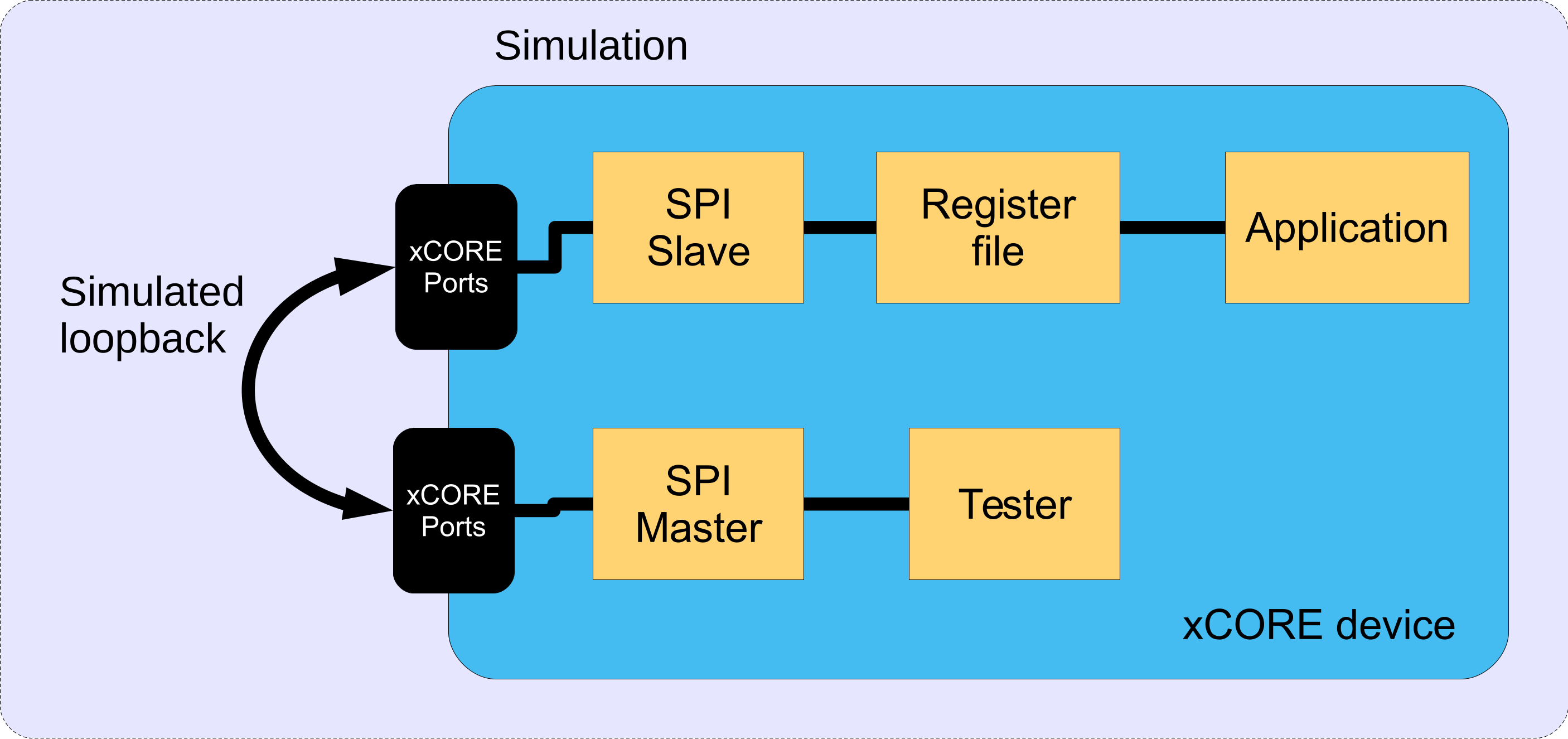
Fig. 12 Block diagram of SPI slave application example
These tasks communicate via the use of xC interfaces. Fig. 13 shows the task and communication structure of the application.
Fig. 13 Task diagram of SPI slave example
Declaring ports
The SPI library connects to external pins via xcore ports. In
main.xc these are declared as variables of type port at the
start of the file:
in port                 p_sclk = on tile[0]: XS1_PORT_1E;
in port                 p_ss   = on tile[0]: XS1_PORT_1F;
out buffered port:32    p_miso = on tile[0]: XS1_PORT_1G;
in buffered port:32     p_mosi = on tile[0]: XS1_PORT_1H;
clock                   cb     = on tile[0]: XS1_CLKBLK_1;
Note
There is also a clock declaration since the slave needs to use an internal clock as well as ports inside the xcore device.
How the ports (e.g. XS1_PORT_1I) relate to external pins will
depend on the exact device being used. See the device datasheet for details.
This application also has an SPI master interface on different ports:
out buffered port:32   p_test_sclk  = on tile[0]: XS1_PORT_1I;
out port               p_test_ss    = on tile[0]: XS1_PORT_1J;
in buffered port:32    p_test_miso  = on tile[0]: XS1_PORT_1K;
out buffered port:32   p_test_mosi  = on tile[0]: XS1_PORT_1L;
The application main() function
Below is the source code for the main function of this application,
which is taken from the source file main.xc
int main(void) {
  interface spi_slave_callback_if i_spi;
  interface reg_if i_reg;
  interface spi_master_if i_spi_master[1];
  par {
    on tile[0]: spi_slave(i_spi, p_sclk, p_mosi, p_miso, p_ss, cb, SPI_MODE_0,
                          SPI_TRANSFER_SIZE_8);
    on tile[0]: reg_file(i_spi, i_reg);
    on tile[0]: app(i_reg);

    // These tasks are not part of the application but a test harness to
    // provide SPI master data which is expected to be looped back in
    // simulation to the SPI slave ports.
    on tile[0]: tester(i_spi_master[0]);
    on tile[0]: spi_master(i_spi_master, 1,
                           p_test_sclk, p_test_mosi, p_test_miso, p_test_ss,
                           1, cb_test);
  }
  return 0;
}
Looking at this in a more detail you can see the following:
The par functionality describes running five separate tasks in parallel; three are for the main application and two are for the tester.
The
spi_slave()task controls the application SPI bus and takes the ports it will use as arguments.The
reg_file()task is connected to theapp()task and thespi_slave()task.The
spi_slave()task has an argument for the mode it expects - in this case Mode 0 (see the SPI library user guide for more details on modes)The
spi_slave()task also has an argumentSPI_TRANSFER_SIZE_8which specifies the size of data chunk it will use when making callbacks to the application.The
spi_master()task controls the test SPI bus and takes different ports to the SPI slave bus as arguments. For details on using SPI master see application note AN00160.
The reg_file() task
The reg_file() task is the main logic of this example. It will
respond to calls from the application and the SPI slave bus whilst
maintaining a set of register values.
The task is marked as [[distributable]] which means it can only
responds to calls from other tasks, rather than resource events.
The main reason for this is so
that the reg_file() task itself does not need a hardware thread of its
own it can use the hardware thread of the task that calls it. See the
XMOS programming guide for details of distributable tasks.
The function takes two arguments, the interface connections to the application task and the SPI slave task:
[[distributable]]
void reg_file(server spi_slave_callback_if i_spi,
              server reg_if i_reg)
{
The reg_if interface has been defined in main.xc earlier. It
defines the functions that the app may call in the reg_file() tasks:
typedef interface reg_if {
  uint8_t get_reg(uint8_t regnum);
  void set_reg(uint8_t regnum, uint8_t value);
} reg_if;
In this case we have two functions - one for reading a register value and one for writing a register value.
The reg_file() task first declares its state - an array to hold
register value, a state variable to hold what stage of an SPI
transaction it is in and the currently addressed register by the SPI bus.
  /* This array holds the register values */
  uint8_t reg_data[NUM_REG] = {0};

  /* This variable holds the current state of the register file with respect
   * to the SPI bus (i.e. what stage of the transaction over SPI it is at).
   */
  enum reg_state_t state = IDLE;

  /* This variable holds the current register being addressed over the SPI
   * bus.
   */
  uint8_t addr = 0;
The state variable is just an integer from the following enum type
defined earlier in the file:
enum reg_state_t {
  WRITE_REG = 0,
  READ_REG = 1,
  WRITE_REG_DATA,
  READ_REG_DATA,
  IDLE
};
The implemented protocol on the SPI bus is as follows:
The master will start a transaction (assert slave select)
It will then send a byte of either a 0 for a write or a 1 for a read.
It will then send the address of the register to read/write
It will then send or receive the value of the register
To implement the protocol logic the reg_file() task must continually react
to events from the SPI slave tasks keeping track of its state,
updating registers and supplying the correct outputs. This is done via
a while(1) loop with an xC select statement inside it. A
select statement will wait and then react to various events or
calls from different tasks - see the XMOS programming guide for more details.
The following cases in the main loop of the function handle this:
  while (1) {
      select {
      /* These cases react to the SPI slave bus. A write from the bus will
       * update the state of the transaction. A read from the bus will get
       * sent the data from the currently addressed register. */
      case i_spi.master_ends_transaction(void):
          state = IDLE;
          break;
      case i_spi.master_requires_data(void) -> uint32_t data:
          data = reg_data[addr];
          break;
      case i_spi.master_supplied_data(uint32_t datum, uint32_t valid_bits):
          switch (state) {
          case IDLE:
              if (datum == WRITE_REG || datum == READ_REG)
                  state = datum;
              break;
          case READ_REG:
              if (datum < NUM_REG) {
                  addr = datum;
                  state = READ_REG_DATA;
              } else {
                  state = IDLE;
              }
              break;
          case READ_REG_DATA:
              // Do nothing with master data during a read data operation.
              break;
          case WRITE_REG:
              if (datum < NUM_REG) {
                  addr = datum;
                  state = WRITE_REG_DATA;
              } else {
                  state = IDLE;
              }
              break;
          case WRITE_REG_DATA:
              reg_data[addr] = datum;
              break;
          }
          break;
We can see that the slave will always send the value of the currently addressed register on every data transfer (this is allowable in the described protocol).
When the SPI master supplies some data to the slave then what happens depends on the current state - either the state variable is updated, the currently addressed register is updated or a register value is updated. This state machine will implement the previously described protocol.
The main select statement also needs to react to request from the
application. The following cases implement this:
      /* The following cases respond to the application when it
       * requests to get/set a register.
       */
      case i_reg.get_reg(uint8_t regnum) -> uint8_t value:
          value = reg_data[regnum];
          break;
      case i_reg.set_reg(uint8_t regnum, uint8_t value):
          reg_data[regnum] = value;
          break;
The app() task
The app() task represents a sample application task that uses the
register file. In this demo, it doesn’t do much - it simple sets one
register and repeatedly polls the value of another register and prints
out its value:
void app(client reg_if reg) {
    uint8_t set_reg_data = 0xed;
    reg.set_reg(0, set_reg_data);
    debug_printf("APP: Set register %u to 0x%x\n", 0, set_reg_data);
    while (1) {
        uint8_t reg_data_read[2];
        delay_microseconds(20);
        reg_data_read[0] = reg.get_reg(0);
        reg_data_read[1] = reg.get_reg(1);
        debug_printf("APP: Register %d is 0x%x, Register %d is 0x%x\n", 0, reg_data_read[0], 1, reg_data_read[1]);
    }
}
Note
The debug_printf function comes from the debug_print.h header supplied by lib_logging. It is a low
memory debug printing function that will print out messages to the
console (either using JTAG or xSCOPE to
communicate to the host via the debug adaptor).
The tester() task
The tester task will send some test data to the SPI master bus. It does this using the SPI master interface to communicate with the SPI master task:
void tester(client spi_master_if spi)
{
    delay_microseconds(50); // Wait for slave to init
    uint8_t val;
    spi.begin_transaction(0, SPI_SPEED_KBPS, SPI_MODE_0);
    spi.transfer8(READ_REG); // READ command
    spi.transfer8(0); // REGISTER 0
    val = spi.transfer8(0); // DATA
    spi.end_transaction(SPI_SS_DELAY_10NS_TICKS);
    debug_printf("SPI MASTER: Read register 0: 0x%x\n", val);

    spi.begin_transaction(0, SPI_SPEED_KBPS, SPI_MODE_0);
    spi.transfer8(WRITE_REG); // WRITE command
    spi.transfer8(1); // REGISTER 1
    spi.transfer8(0xac); // DATA
    spi.end_transaction(SPI_SS_DELAY_10NS_TICKS);
    printstr("SPI MASTER: Set register 1 to 0xAC\n");

    delay_microseconds(100);
    _Exit(0);
}
Building
The following section assumes that the XMOS XTC tools has been downloaded and installed (see README for required version).
Installation instructions can be found here. Particular attention should be paid to the section Installation of required third-party tools.
The application uses the XMOS build and dependency system, xcommon-cmake. xcommon-cmake is bundled with the XMOS XTC tools. It runs on the xcore.ai evaluation kit, XK-EVK-XU316.
To configure the build, run the following from an XTC command prompt:
cd examples
cd app_spi_slave
cmake -G "Unix Makefiles" -B build
Any missing dependencies will be downloaded by the build system at this configure step.
Finally, the application binaries can be built using xmake:
xmake -j -C build
Running
To run the application return to the /examples/app_spi_slave directory and run the following command:
xsim --xscope '-offline trace.xmt' bin/app_spi_slave.xe  \
--trace-plugin VcdPlugin.dll '-tile tile[0] -o trace.vcd -xe bin/app_spi_slave.xe \
-ports -functions -cores -instructions' --plugin LoopbackPort.dll \
'-port tile[0] XS1_PORT_1I 1 0 -port tile[0] XS1_PORT_1E 1 0 \
-port tile[0] XS1_PORT_1J 1 0 -port tile[0] XS1_PORT_1F 1 0 \
-port tile[0] XS1_PORT_1K 1 0 -port tile[0] XS1_PORT_1G 1 0 \
-port tile[0] XS1_PORT_1L 1 0 -port tile[0] XS1_PORT_1H 1 0'
Note
This command line is provided as a file in the /examples/app_spi_slave directory under the filename simulate_cmd.txt.
You can rename this file to simulate_cmd.sh or simulate_cmd.bat and run it directly, depending on your host OS.
As application runs that reads a value from the SPI connected WiFi chip and prints the following output to the console:
APP: Set register 0 to 0xED
APP: Register 0 is 0xED, Register 1 is 0x0
APP: Register 0 is 0xED, Register 1 is 0x0
SPI MASTER: Read register 0: 0xED
APP: Register 0 is 0xED, Register 1 is 0x0
SPI MASTER: Set register 1 to 0xAC
APP: Register 0 is 0xED, Register 1 is 0xAC
APP: Register 0 is 0xED, Register 1 is 0xAC
APP: Register 0 is 0xED, Register 1 is 0xAC
Both registers were initialised to 0x00 so you can see the successful application side write to register 0 of value 0xED, followed by the SPI master read of that register shortly afterwards. You can also see that the SPI master writes to register 1 with the value of 0xAC which is then successfully read by the application.
If you wish, you can also view the simulation in a VCD (Voltage Change Description) viewer, such as gtkwave, by running the following command:
gtkwave slave_simulation.gtkw
This will show the four SPI lines and zoom into the section where the SPI transactions occur, as can be seen in Fig. 14.
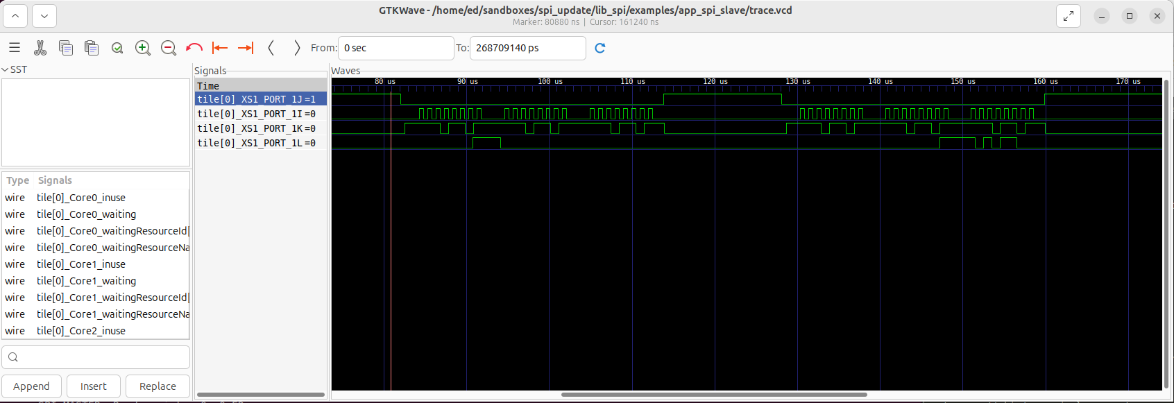
Fig. 14 VCD waveform trace for SPI slave with registers simulation
Resource Usage
Each of the SPI implementations use a number of xcore resources which include ports, clock-blocks and may include hardware threads. The table Table 6
configuration |
api |
pins |
ports |
threads |
|---|---|---|---|---|
Master (synchronous, zero clock blocks) |
spi_master(i, 1, p_sclk, p_mosi, p_miso, p_ss, 1, null); |
4 |
3 * 1-bit, 1 * any-bit |
0 |
Master (synchronous, one clock block) |
spi_master(i, 1, p_sclk, p_mosi, p_miso, p_ss, 1, cb); |
4 |
3 * 1-bit, 1 * any-bit |
0 |
Master (asynchronous) |
spi_master_async(i, 1, p_sclk, p_mosi, p_miso, p_ss, 1, cb); |
4 |
3 * 1-bit, 1 * any-bit |
1 |
Slave (32 bit transfer mode) |
spi_slave(i, p_sclk, p_mosi, p_miso, p_ss, cb, SPI_MODE_0, SPI_TRANSFER_SIZE_32); |
4 |
4 (1-bit) |
1 |
Slave (8 bit transfer mode) |
spi_slave(i, p_sclk, p_mosi, p_miso, p_ss, cb, SPI_MODE_0, SPI_TRANSFER_SIZE_8); |
4 |
4 (1-bit) |
1 |
The number of pins is reduced if either of the data lines are not required.
API Reference
Master API
All SPI master functions can be accessed via the spi.h header:
#include "spi.h"
You will also have to add lib_spi to the application’s APP_DEPENDENT_MODULES list in
CMakeLists.txt, for example:
set(APP_DEPENDENT_MODULES "lib_spi")
Supporting types
The following type is used to configure the SPI components.
-
enum spi_mode_t
This type indicates what clocking mode a SPI component should use
Values:
-
enumerator SPI_MODE_0
SPI Mode 0 - Polarity = 0, Phase = 0
-
enumerator SPI_MODE_1
SPI Mode 1 - Polarity = 0, Phase = 1
-
enumerator SPI_MODE_2
SPI Mode 2 - Polarity = 1, Phase = 0
-
enumerator SPI_MODE_3
SPI Mode 3 - Polarity = 1, Phase = 1
-
enumerator SPI_MODE_0
-
struct spi_master_ss_clock_timing_t
This type contains timing settings for SS assert to clock delay and last clock to SS de-assert delay. The unit is reference timer ticks which is nominally 10 ns. The maximum setting is 65535 which equates to 655 us, over which the setting will overflow back to zero
-
struct spi_master_miso_capture_timing_t
This type contains timing settings for capturing the MISO pin for SPI master. When the SPI clock is above 20MHz it is usually necessary to delay the sampling of the MISO pin. These settings can be coarse grained using miso_sample_delay setting which increments in SPI half clocks or fine grained in units of core clock (eg. 600 MHz -> 1.66 ns) using the miso_pad_delay setting.
See the following document for details on xcore.ai port timing: https://www.xmos.com/documentation/XM-014231-AN/html/rst/index.html
Creating an SPI master instance
- void spi_master(
- SERVER_INTERFACE(spi_master_if, i[num_clients]),
- static_const_size_t num_clients,
- out_buffered_port_32_t sclk,
- NULLABLE_RESOURCE(out_buffered_port_32_t, mosi),
- NULLABLE_RESOURCE(in_buffered_port_32_t, miso),
- out_port p_ss,
- static_const_size_t num_slaves,
- NULLABLE_RESOURCE(clock, clk),
Task that implements the SPI proctocol in master mode that is connected to a multiple slaves on the bus.
Each slave must be connected to using the same SPI mode.
You can access different slave devices over the interface connection using the device_index parameter of the interface functions. The task will allocate the device indices in the order of the supplied array of slave select ports.
- Parameters:
i – An array of interface connection to the clients of the task.
num_clients – The number of clients connected to the task.
clk – a clock block used by the task.
sclk – The SPI clock port.
mosi – The SPI MOSI (master out, slave in) port.
miso – The SPI MISO (master in, slave out) port.
p_ss – A port connected to the slave select signals of the slave. Multiple slaves may be supported by specifying, for example, a 4-bit port. Please specify mapping of bits to slaves using i.set_ss_port_bit().
num_slaves – The number of slave devices on the bus.
clk – A clock for the component to use. May be set to null if low speed operation is acceptable.
- void spi_master_async(
- SERVER_INTERFACE(spi_master_async_if, i[num_clients]),
- static_const_size_t num_clients,
- out_buffered_port_32_t sclk,
- NULLABLE_RESOURCE(out_buffered_port_32_t, mosi),
- in_buffered_port_32_t miso,
- out_port p_ss,
- static_const_size_t num_slaves,
- clock clk,
SPI master component for asynchronous API.
This component implements SPI and allows a client to connect using the asynchronous SPI master interface.
- Parameters:
i – an array of interface connection to the clients of the task.
num_clients – the number of clients connected to the task.
sclk – the SPI clock port.
mosi – the SPI MOSI (master out, slave in) port.
miso – the SPI MISO (master in, slave out) port.
p_ss – a port of any width which outputs the slave select signals
num_slaves – The number of slave devices on the bus.
clk – a clock block for the component to use.
SPI master interface
- group Spi_master_if
This interface allows clients to interact with SPI master task.
Methods for synchronous SPI master interface.
Functions
- void begin_transaction(
- unsigned device_index,
- unsigned speed_in_khz,
- spi_mode_t mode,
Begin a transaction.
This will start a transaction on the bus. During a transaction, no other client to the SPI component can send or receive data. If another client is currently using the component then this call will block until the bus is released.
- Parameters:
device_index – The index of the slave device to interact with.
speed_in_khz – The speed that the SPI bus should run at during the transaction (in kHZ). When using the version with clockblock, the minimum speed is 100 kHz.
mode – The mode of spi transfers during this transaction.
-
void end_transaction(unsigned ss_deassert_time)
End a transaction.
This ends a transaction on the bus and releases the component to other clients.
- Parameters:
ss_deassert_time – The minimum time in reference clock ticks between assertions of the selected slave select. This time will be ignored if the next transaction is to a different slave select.
-
uint8_t transfer8(uint8_t data)
Transfer a byte over the SPI bus.
This function will transmit and receive 8 bits of data over the SPI bus. The data will be transmitted least-significant bit first.
- Parameters:
data – The data to transmit the MOSI port.
- Returns:
The data read in from the MISO port.
-
uint32_t transfer32(uint32_t data)
Transfer a 32-bit word over the SPI bus.
This function will transmit and receive 32 bits of data over the SPI bus. The data will be transmitted least-significant bit first and most significant byte first (big endian)
- Parameters:
data – The data to transmit the MOSI port.
- Returns:
The data read in from the MISO port.
- void transfer_array(
- NULLABLE_ARRAY_OF(const uint8_t, data_out),
- NULLABLE_ARRAY_OF(uint8_t, data_in),
- static_const_size_t num_bytes,
Transfer an array of bytes over the SPI interface.
This function will transmit and receive 32 bits of data over the SPI bus. The data will be transmitted least-significant bit first in byte order in memory. Note that XMOS uses little endian and so 32b data etc. may need byteswap() first.
- Parameters:
data_out – Reference to data to transmit the MOSI port. May be null if only a read is needed.
data_in – Reference to data to receive from the MISO port. May be null if only a write is needed.
num_bytes – Constant value of the size of the array to be transferred.
-
void set_ss_port_bit(unsigned device_index, unsigned ss_port_bit)
Sets the bit of port which is used for slave select (> 1b port type only) and only for spi_master. spi_master sets all bits in each port high/low
The default value (if this is not called) is the bit number is equal to the device_index (device 0-> bit 0, device 1-> bit 1 etc.).
- Parameters:
device_index – The index of the device for which the port bit is to be set.
ss_port_bit – Which bit number in the port to use for slave select.
- void set_miso_capture_timing(
- unsigned device_index,
- spi_master_miso_capture_timing_t miso_capture_timing,
Configures the timing parameters for MISO capture. At frequencies above 20 MHz it is likely that some capture delays will need to be introduced to ensure setup and hold times are met. These settings only affect the fast SPI master which uses a clock block.
See the following document for details on xcore.ai port timing: https://www.xmos.com/documentation/XM-014231-AN/html/rst/index.html
- Parameters:
device_index – The index of the device for which the MISO timing is to be set.
miso_capture_timing – A structure of type spi_master_miso_capture_timing_t with the desired settings.
- void set_ss_clock_timing(
- unsigned device_index,
- spi_master_ss_clock_timing_t ss_clock_timing,
Configures the timing settings for SS assert to clock delay, and last clock to SS de-assert delay. The unit is reference timer ticks which is nominally 10 ns. The maximum setting is 65535 which equates to 655 us over which the setting will overflow back to zero. These settings only affect the fast SPI master which uses a clock block.
- Parameters:
device_index – The index of the device for which the SS timing is to be set.
ss_clock_timing – A structure of type spi_master_ss_clock_timing_t with the desired settings.
-
void shutdown(void)
Shut down the SPI master interface server.
SPI master asynchronous interface
- group Spi_master_async_if
Asynchronous interface to an SPI component.
This interface allows programs to offload SPI bus transfers to another task. An asynchronous notification occurs when the transfer is complete.
Methods for asynchronous SPI master interface.
Functions
- void begin_transaction(
- unsigned device_index,
- unsigned speed_in_khz,
- spi_mode_t mode,
Begin a transaction.
This will start a transaction on the bus. During a transaction, no other client to the SPI component can send or receive data. If another client is currently using the component then this call will block until the bus is released.
- Parameters:
device_index – The index of the slave device to interact with.
speed_in_khz – The speed that the SPI bus should run at during the transaction (in kHZ). The minimum speed is 100 kHz.
mode – The mode of spi transfers during this transaction
-
void end_transaction(unsigned ss_deassert_time)
End a transaction.
This ends a transaction on the bus and releases the component to other clients.
- Parameters:
ss_deassert_time – The minimum time in reference clock ticks between assertions of the selected slave select. This time will be ignored if the next transaction is to a different slave select.
- void init_transfer_array_8(
- uint8_t_movable_ptr_t inbuf,
- uint8_t_movable_ptr_t outbuf,
- size_t nbytes,
Initialize Transfer an array of bytes over the SPI bus.
This function will initialize a transmit of 8 bit data over the SPI bus.
- Parameters:
inbuf – A movable pointer that is moved to the other task pointing to the buffer area to fill with data. If this parameter is NULL then the incoming data of the transfer will be discarded.
outbuf – A movable pointer that is moved to the other task pointing to the buffer area to with data to transmit. If this parameter is NULL then the outgoing data of the transfer will consist of undefined values.
nbytes – The number of bytes to transfer over the bus.
- void init_transfer_array_32(
- uint32_t_movable_ptr_t inbuf,
- uint32_t_movable_ptr_t outbuf,
- size_t nwords,
Initialize Transfer an array of bytes over the SPI bus.
This function will initialize a transmit of 32 bit data over the SPI bus.
- Parameters:
inbuf – A movable pointer that is moved to the other task pointing to the buffer area to fill with data. If this parameter is NULL then the incoming data of the transfer will be discarded.
outbuf – A movable pointer that is moved to the other task pointing to the buffer area to with data to transmit. If this parameter is NULL then the outgoing data of the transfer will consist of undefined values.
nwords – The number of words to transfer over the bus.
-
void transfer_complete(void)
Transfer completed notification.
This notification occurs when a transfer is completed.
- void retrieve_transfer_buffers_8(
- REFERENCE_PARAM(uint8_t_movable_ptr_t, inbuf),
- REFERENCE_PARAM(uint8_t_movable_ptr_t, outbuf),
Retrieve transfer buffers.
This function should be called after the transfer_complete() notification and will return the buffers given to the other task by init_transfer_array_8().
- Parameters:
inbuf – A movable pointer that will be set to the buffer pointer that was filled during the transfer.
outbuf – A movable pointer that will be set to the buffer pointer that was transmitted during the transfer.
- void retrieve_transfer_buffers_32(
- REFERENCE_PARAM(uint32_t_movable_ptr_t, inbuf),
- REFERENCE_PARAM(uint32_t_movable_ptr_t, outbuf),
Retrieve transfer buffers.
This function should be called after the transfer_complete() notification and will return the buffers given to the other task by init_transfer_array_32().
- Parameters:
inbuf – A movable pointer that will be set to the buffer pointer that was filled during the transfer.
outbuf – A movable pointer that will be set to the buffer pointer that was transmitted during the transfer.
-
void set_ss_port_bit(unsigned device_index, unsigned ss_port_bit)
Sets the bit of port which is used for slave select (> 1b port type only) and only for spi_master. spi_master sets all bits in each port high/low
The default value (if this is not called) is the bit number is equal to the device_index (0->0, 1->1 etc.).
- Parameters:
device_index – The index of the device for which the port bit is to be set.
ss_port_bit – Which bit number in the port to use for slave select.
- void set_miso_capture_timing(
- unsigned device_index,
- spi_master_miso_capture_timing_t miso_capture_timing,
Configures the timing parameters for MISO capture. At frequencies above 20 MHz it is likely that some capture delays will need to be introduced to ensure setup and hold times are met.
See the following document for details on xcore.ai port timing: https://www.xmos.com/documentation/XM-014231-AN/html/rst/index.html
- Parameters:
device_index – The index of the device for which the MISO timing is to be set.
miso_capture_timing – A structure of type spi_master_miso_capture_timing_t with the desired settings.
- void set_ss_clock_timing(
- unsigned device_index,
- spi_master_ss_clock_timing_t ss_clock_timing,
Configures the timing settings for SS assert to clock delay, and last clock to SS de-assert delay. The unit is reference timer ticks which is nominally 10 ns. The maximum setting is 65535 which equates to 655 us over which the setting will overflow back to zero.
- Parameters:
device_index – The index of the device for which the SS timing is to be set.
ss_clock_timing – A structure of type spi_master_ss_clock_timing_t with the desired settings.
-
void shutdown(void)
Shut down the SPI master interface server. Must be done after all transactions are complete to avoid leaving moveable pointers in the wrong place.
Slave API
All SPI slave functions can be accessed via the spi.h header:
#include <spi.h>
You will also have to add lib_spi to the
APP_DEPENDENT_MODULES field of your application CMakefile.
Creating an SPI slave instance
- void spi_slave(
- CLIENT_INTERFACE(spi_slave_callback_if, spi_i),
- in_port p_sclk,
- in_buffered_port_32_t p_mosi,
- NULLABLE_RESOURCE(out_buffered_port_32_t, p_miso),
- in_port p_ss,
- clock clk,
- static_const_spi_mode_t mode,
- static_const_spi_transfer_type_t transfer_type,
SPI slave component.
This function implements an SPI slave bus.
- Parameters:
spi_i – The interface to connect to the user of the component. The component acts as the client and will make callbacks to the application.
p_sclk – The SPI clock port.
p_mosi – The SPI MOSI (master out, slave in) port.
p_miso – The SPI MISO (master in, slave out) port.
p_ss – The SPI SS (slave select) port.
clk – Clock to be used by the component.
mode – The SPI mode of the bus.
transfer_type – The type of transfer the slave will perform: either
SPI_TRANSFER_SIZE_8orSPI_TRANSFER_SIZE_32.
The SPI slave interface API
- group Spi_slave_callback_if
This interface allows clients to interact with SPI slave tasks by completing callbacks that show how to handle data.
Methods for SPI slave interface.
Functions
-
void master_ends_transaction(void)
This callback will get called when the master de-asserts on the slave select line to end a transaction.
-
uint32_t master_requires_data(void)
This callback will get called when the master initiates a bus transfer or when more data is required during a transaction. The application must supply the data to transmit to the master. Data is transmitted with the least significant bit first. If the master completes the transaction before 8/32 bits ( depending on SPI_TRANSFER_SIZE_8 or SPI_TRANSFER_SIZE_32) are transferred and the remaining bits are discarded.
- Returns:
the 8-bit or 32-bit value to transmit.
-
void master_supplied_data(uint32_t datum, uint32_t valid_bits)
This callback will get called after a transfer. It will occur after every 8 bits transferred if the slave component is set to
SPI_TRANSFER_SIZE_8. If the component is set toSPI_TRANSFER_SIZE_32then it will occur if the master ends the transaction before 32 bits are transferred.- Parameters:
datum – the data received from the master.
valid_bits – the number of valid bits of data received from the master.
-
void request_shutdown(void)
Request shut down the SPI slave interface client.
-
void shutdown_complete(void)
Acknowledgment that the SPI slave task has been shutdown.
-
void master_ends_transaction(void)