lib_i2s: I2S/TDM library#
Introduction#
lib_i2s allows interfacing to I²S or TDM (Time Division Multiplexed) buses via xcore ports
and can act either act as I²S controller (previously termed master) or target (previously termed
slave) or TDM controller.
I²S and TDM are digital data streaming interfaces particularly appropriate for transmission of audio data.
I²S fundamentals#
I²S is a protocol between two devices where one is the controller (or master) and one is the target (or slave) . The protocol is made up of three signals shown in Table 1.
SCK |
Serial clock (or “bit clock”). Clock line controlling data timing. Driven by the controller. |
WS |
Word select (or “left/right clock”). Channel synchronisation signal. Driven by the controller. |
SD |
Serial Data, driven either the target or controller depending on the data direction. There may be several data lines in differing directions. |
The protocol may also include additional lines shown in Table 2.
MCLK |
Master clock. (typically 256 x WS); not part of the standard, but is commonly included for synchronising the internal operation of the analog/digital converters |
Key parameters of of a I²S protocol are shown in Table 3.
MCLK_BCLK_RATIO |
The fixed ratio between the master clock and the bit clock. |
MODE |
The mode - the alignment of the data respective to WS |
NUM_DATA_BITS |
The number of bits in a data word; this is usually 32, but can be adjusted to any value below 32 if required when using one bit ports for I/O. |
I²S has several modes based on data alignment and channel configuration:
Standard (Philips): Data is aligned with the Word Select (WS) signal change, commonly used with PCM audio.
Left-Justified: Data starts immediately with the WS change, aligning MSB (Most Significant Bit) with the WS transition.
Right-Justified: Data is right-aligned with the WS, with the LSB (Least Significant Bit) ending at the WS transition.
Note
lib_i2s currently only supports standard” and “left-justified” modes.
The controller signals data transfer should occur by a transition on the WS (LRCLK) line. In standard mode (shown in Fig. 1) data is transferred on the second falling edge after the WS transitions.
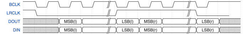
Fig. 1 I²S Mode#
In Left Justified Mode (shown in Fig. 2) the data is transferred on the next falling edge after the WS transition.
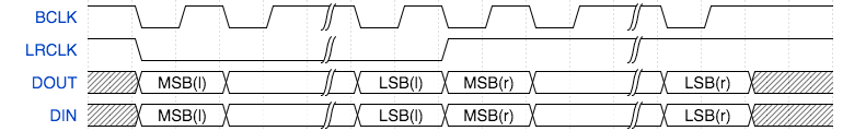
Fig. 2 Left Justified Mode#
In either case the signal multiplexes two channels of data onto one data line. When the WS is low, the left channel is transmitted. When the WS is high, the right channel is transmitted.
All data is transmitted most significant bit first.
Note
Right Justified mode can be attained by setting the lib_i2s to Left Justified mode to
align data to the WS signal and then the data should be right shifted appropriately by the
application before being provided to lib_i2s.
Resource usage#
The I²S and TDM modules use one hardware thread and between 1.6 and 2.1kB of memory. There may be spare processing time available in the callbacks of I²S and TDM. IO usage is 1 x 1b port for each signal or 4b ports for data in some cases.
Connecting I²S signals to the xcore device#
The I²S wires need to be connected to the xcore device as shown in Fig. 3 and Fig. 4. The signals can be connected to any one bit port on the device provided that they do not overlap any other used ports and are all on the same tile. In addition, four bit ports may also be used to connect to up to four signals of input or output with the same constraints as above.
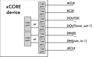
Fig. 3 I²S connection to the xcore device (xcore as I²S controller)#
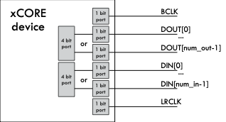
Fig. 4 I²S connection to the xcore device (xcore as I²S target)#
If only one data direction is required then the DOUT or DIN lines can be omitted.
Warning
The use of four-bit ports over one-bit ports will lead to some restrictions in supported frequencies.
I²S controller speeds and performance#
The speed and number of data wires that can be driven by the lib_i2s running as a I²S controller
(master) depends on the speed of the thread that runs the code and the amount of processing that
occurs in the user callbacks for handling the data from the library.
I²S controller uses hardware clock dividers and an efficient callback interface to achieve high throughputs. This also permits the use of non-32bit data word lengths if needed. Table 4 shows the known working configurations when using one-bit ports for the data lines:
MCLK FREQ (MHz) |
MCLK/BCLK RATIO |
DATA WORD (bits) |
SAMPLE FREQ (Hz) |
MAX IN (chans) |
MAX OUT (chans) |
|---|---|---|---|---|---|
12.288 |
32, 16, 8, 4, 2 |
32 |
6000 - 96000 |
4 (8) |
4 (8) |
24.576 |
64, 32, 16, 8, 4, 2 |
32 |
6000 - 192000 |
1 (2) |
1 (2) |
100 |
344 |
24 |
6056 |
4 (8) |
4 (8) |
250 |
432, 216, 108, 52, 24 |
24 |
12056 - 217013 |
4 (2) |
4 (2) |
12.288 |
64, 32, 16, 8, 4, 2 |
16 |
6000 - 192000 |
4 (8) |
4 (8) |
24.576 |
128, 64, 32, 16, 8, 4 |
16 |
6000 - 192000 |
1 (2) |
1 (2) |
12.288 |
128, 64, 32, 16, 8, 4 |
8 |
6000 - 192000 |
4 (8) |
4 (8) |
24.576 |
256, 128, 64, 32, 16, 8 |
8 |
6000 - 192000 |
1 (2) |
1 (2) |
Table 5 shows the known working configurations when using four-bit ports for the data lines:
MCLK FREQ (MHz) |
MCLK/BCLK RATIO |
DATA WORD (bits) |
SAMPLE FREQ (Hz) |
MAX IN (chans) |
MAX OUT (chans) |
|---|---|---|---|---|---|
12.288 |
32, 16, 8, 4, 2 |
32 |
6000 - 96000 |
4 (8) |
4 (8) |
24.576 |
64, 32, 16, 8, 4, 2 |
32 |
6000 - 192000 |
1 (2) |
1 (2) |
Note
If running at higher rates such as 768 kHz, it may be necessary to modify the port timing delays to ensure proper sampling of the data and WS lines. There are methods for doing this using I/O pad/pin and/or sampling delays, however, this is beyond the scope of this document. Please consult I/O timings for xcore-200 and I/O timings for xcore.ai for further information.
I²S target speeds and performance#
The speed and number of data wires that can be driven by lib_i2s running as a target (slave)
depends on the speed of the thread that runs the code and the amount of processing that occurs in
the user callbacks for handling the data from the library.
The table Table 6 shows the known working configurations when using a one-bit port. Other configurations may be possible depending on performance:
BCLK FREQ (MHz) |
DATA WORD (bits) |
SAMPLE FREQ (Hz) |
NUM IN (num channels) |
NUM OUT (num channels) |
|---|---|---|---|---|
12.288 |
32 |
192000 |
4 (8) |
4 (8) |
12.288 |
16 |
192000 |
4 (8) |
4 (8) |
12.288 |
8 |
192000 |
4 (8) |
4 (8) |
The table Table 7 shows the known working configurations when using a four-bit port. Other configurations may be possible depending on performance:
BCLK FREQ (MHz) |
DATA WORD |
SAMPLE FREQ |
NUM IN (num channels) |
NUM OUT (num channels) |
|---|---|---|---|---|
12.288 |
32 |
192000 |
4 (8) |
4 (8) |
Note
A master-clock input is not required when operating as an I²S target
TDM fundamentals#
I²S TDM (Inter-IC Sound Time Division Multiplexing) is a specialised protocol in digital audio systems used for transmitting audio data. It’s a combination of the I²S protocol, commonly used for digital audio data transfer, with Time Division Multiplexing (TDM), which allows multiple audio channels to be sent over a single data line.
It is a protocol between devices where one is the controller (master) and one or more are the targets (slaves).
In I²S TDM mode, multiple channels (typically 8) are packed within each frame, with each channel assigned a specific time slot. By using TDM, audio systems can reduce the number of data lines required, consolidating multiple audio channels onto one I²S bus.
The protocol comprises three signals:
- Bit clock (BCLK)
The Bit Clock line provides the clock signal for each bit of data.
It determines the speed at which bits are transmitted across the data line.
Each cycle of BCLK corresponds to the transmission of one bit in the data stream.
- Word Clock (WS) or Frame Sync (FS)
The Word Select (sometimes called Frame Sync) line is used to mark the beginning of each frame in TDM.
In standard I2S, this line is used to distinguish left and right channels. But in TDM, it signals the start of a frame that could contain multiple channels.
Each complete WS cycle (high and low) represents a full frame of multiple audio channels.
- Serial Data (SD) or Data Line
The Serial Data line carries the actual audio data.
In TDM, this data line contains time-division multiplexed data from multiple channels within each frame, with each channel assigned a specific time slot.
Audio samples from each channel are transmitted sequentially in their designated slots within a frame.
Unlike I²S there is no formal specification for TDM and implementations vary between manufacturers. The configuration of a TDM signal depends on the parameters shown in Table 8. Manipulation of these values allows for compatibility with a large range of devices.
CHANNELS_PER_FRAME |
The number of channels multiplexed into a frame on the data line. |
FSYNC_OFFSET |
The number of bits between the frame sync signal transitioning and data being driven on the data line(s). |
FSYNC_LENGTH |
The number of bits that the frame sync signal stays high for when signaling frame start. |
Fig. 5 and Fig. 6 show example waveforms for TDM with different offset and sync length values.

Fig. 5 TDM signal (sync offset 0, sync length 1)#
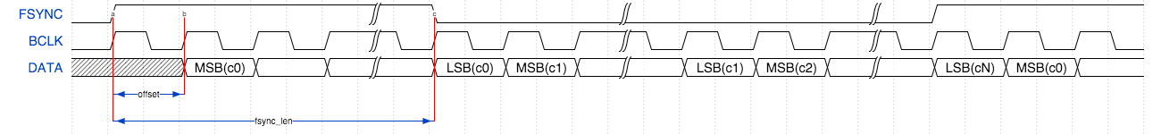
Fig. 6 TDM signal (sync offset 1, sync length 32)#
The controller signals a frame by driving the FSYNC signal high. After a delay of FSYNC_OFFSET bits, data is driven. Data is driven most significant bit first. First, 32 bits of data from Channel 0 is driven, then 32 bits from channel 1 up to channel N (when N is CHANNELS_PER_FRAME). The next frame is then signaled.
Connecting TDM signals to the xcore device#
The TDM lines need to be connected to the xcore device as shown in Fig. 7. The signals can be connected to any one bit ports on the device provided they do not overlap any other used ports and are all on the same tile.
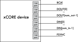
Fig. 7 TDM connection to the xCORE device#
If only one data direction is required then the DOUT or DIN lines can be omitted.
TDM speeds and performance#
The speed and number of data wires that can be driven by the I²S library running as TDM controller depends on the speed of the thread that runs the code and the amount of processing that occurs in the user callbacks for handling the data from the library. Table 9 show configurations that are known to work for small amounts of callback processing. Other speeds will be achievable depending on the amount of processing in the application and the thread speed.
BCLK FREQ (MHz) |
CHANNELS PER FRAME |
SAMPLE FREQ (Hz) |
NUM IN (num channels) |
NUM OUT (num channels) |
|---|---|---|---|---|
12.288 |
8 |
48000 |
2 (16) |
2 (16) |
6.144 |
4 |
48000 |
4 (16) |
4 (16) |
Usage#
lib_i2s is intended to be used with XCommon CMake,
the XMOS application build and dependency management system.
In order to use lib_i2s it needs to be added to the APP_DEPENDENT_MODULES list in the
application CMakeLists.txt file, for example:
set(APP_DEPENDENT_MODULES "lib_i2s")
Applications should then include the i2s.h header file.
The callback interface#
All major functions in the lib_i2s operate by controlling the I²S or TDM bus in a thread of
a xcore device. The library will then make callbacks to the application when it receives a frame
of samples or requires a frame of samples to send.
I²S controller usage#
A template application task is shown below. The specific contents of each callback will depend on the application.
void my_application(server i2s_frame_callback_if i_i2s) {
  while (1) {
    select {
      case i_i2s.init(i2s_config_t &?i2s_config, tdm_config_t &?tdm_config):
        i2s_config.mclk_bclk_ratio = (MASTER_CLOCK_FREQUENCY / (SAMPLE_FREQUENCY*2*DATA_BITS));
        i2s_config.mode = I2S_MODE_LEFT_JUSTIFIED;
        // Complete setup
        break;
      case i_i2s.restart_check() -> i2s_restart_t restart:
        // Inform the I2S slave whether it should restart or exit
        restart = I2S_NO_RESTART;
        break;
      case i_i2s.receive(size_t num_in, int32_t samples[num_in]):
        // Handle a received sample
        break;
      case i_i2s.send(size_t num_out, int32_t samples[num_out]):
        // Provide a sample to send
        break;
    }
  }
}
The initialisation callback will provide configuration structures relevant to the communication bus being used. The application can set the parameters of the bus (MCLK/BCLK ratio, WS alignment etc.) at this point.
The I²S controller (master) task is instantiated as a parallel task that run in a par statement. The
application can connect via the i2s_frame_callback_if interface connection. For example,
the following code instantiates an I²S controller component and connects to it.
int main(void) {
  i2s_frame_callback_if i_i2s;

  par {
    i2s_frame_master(i_i2s, p_dout, 2, p_din, 2, DATA_BITS, p_sck, p_ws, p_mclk, bclk);
    my_application(i_i2s);
  }
  return 0;
}
I²S target usage#
The I²S target (slave) task is instantiated as a parallel task that runs in a par statement.
The application can connect via the i2s_frame_callback_if interface connection. For example,
the following code instantiates an I²S target component and connects to it.
out buffered port:32 p_dout[2] = {XS1_PORT_1D, XS1_PORT_1E};
in buffered port:32 p_din[2] = {XS1_PORT_1I, XS1_PORT_1J};
in port p_bclk = XS1_PORT_1A;
in buffered port:32 p_lrclk = XS1_PORT_1C;

clock bclk = XS1_CLKBLK_1;

int main(void) {
  interface i2s_frame_callback_if i_i2s;

  par {
    i2s_frame_slave(i_i2s, p_dout, 2, p_din, 2, DATA_BITS, p_bclk, p_lrclk, bclk);
    my_application(i_i2s);
  }
  return 0;
}
The target API has an additional configuration option to sample SD and WS on the falling edge of bit clock, instead of rising edge. Data is then output on rising edge instead of falling edge. This option is useful with non-standard controllers that invert their bit clock.
TDM usage#
The TDM controller task is instantiated as a parallel task that runs in a par statement.
The application can connect via the tdm_callback_if interface connection. For example,
the following code instantiates a TDM controller component and connects to it.
out buffered port:32 p_dout[2] = {XS1_PORT_1D, XS1_PORT_1E};
in buffered port:32 p_din[2] = {XS1_PORT_1I, XS1_PORT_1K};
in port p_bclk = XS1_PORT_1A;
out buffered port:32 p_fsync = XS1_PORT_1C;

clock bclk = XS1_CLKBLK_1;

int main(void) {
  tdm_callback_if i_tdm;
  configure_clock_src(bclk, p_bclk);

  par {
    tdm_master(i_tdm, p_fsync, p_dout, 1, p_din, 1, bclk);
    my_application(i_tdm);
  }
  return 0;
}
The callback interface for TDM numbers the channels being sent/received for the send and receive callbacks. There is a fixed mapping from these channel indices to the physical interface being used.
TDM channel numbering#
The data words within TDM frames are assigned sequentially from the start of the frame. Each data line will have its channel numbers assigned in the order that the ports are provided in the data in and data out array arguments to the component.
For example, a system with 2 data out ports and 2 data in ports is declared as:
out buffered port:32 p_dout[2] = {XS1_PORT_1A, XS1_PORT_1B};
in buffered port:32 p_din[2] = {XS1_PORT_1E, XS1_PORT_1F};
With the number of channels per frame as 4, the samples will be numbered as indicated in Fig. 8:
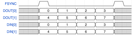
Fig. 8 TDM channel numbering#
Callback sequences#
The I²S implementations have a simple sequence. Table 10 shows an example sequence.
Initial send: |
Init, Send All |
Frame: |
Restart check, Send All, Receive All |
Frame: |
Restart check, Send All, Receive All |
… |
… |
Frame: |
Restart check, Send All, Receive All |
Final receive: |
Restart check (I2S_RESTART), Receive All |
When using TDM, the receive callbacks for a channel occur after the send callbacks. The receive callback for the last channel of the frame will occur after the send callback for the next frame. After a restart request a tail of receive callbacks for the last channel of the final frame will occur. Table 11 shows an example TDM callback sequence for two data lines in and out with four channels per frame.
S0 S4 S1 S5 R0 R4 S2 S6 R1 R5 S3 S7 R2 R6 |
S0 S4 R3 R7 S1 S5 R0 R4 S2 S6 R1 R5 S3 S7 R2 R6 |
… |
S0 S4 R3 R7 S1 S5 R0 R4 S2 S6 R1 R5 S3 S7 R2 R6 |
S0 S4 R3 R7 S1 S5 R0 R4 S2 S6 R1 R5 S3 S7 R2 R6 |
R3 R7 |
In both cases the components attempt to distribute the calling of the callbacks evenly within the frame to allow processing to occur throughout the frame evenly.
The restart_check callback is called once per frame to allow the
application to request a restart/shutdown of the data bus.
Clock configuration#
For the TDM components it is the application’s responsibility to set up and start the internal clock used for the master clock before calling the component.
For example, the following code configures a clock to be based of an incoming data wire and starts the clock:
configure_clock_src(mclk, p_mclk);
start_clock(mclk);
For more information on configuring clocks see the XMOS XTC tools user guide
Examples#
Various example example applications are provided along side the lib_i2s that demonstrate basic
usage.
These are located in the examples directory.
Loopback demos#
Two fully fledged demonstration applications are included in the accompanying examples that
implement an audio loopback using I²S.
One where xcore operates as a controller (or master) and another where the xcore operates
as a target (or slave).
These are app_i2s_frame_loopback_demo and app_i2s_frame_slave_loopback_demo respectively.
These example applications run on the XMOS XU316 Multichannel Audio board (XK-AUDIO-316-MC).
This section documents app_i2s_frame_loopback in detail, however, much of the detail is shared
with app_i2s_frame_slave_loopback_demo.
Block diagram#
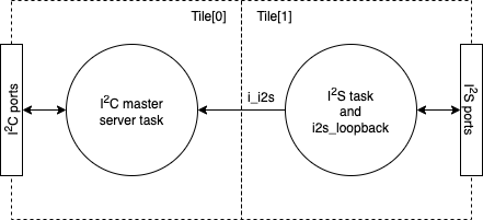
Fig. 9 Application block diagram#
The main application fits within one thread with an additional remote I²C task to allow the audio hardware to be configured remotely from the other tile. This required due to the IO arrangement of the XK-AUDIO-316-MC board.
A board support library, lib_board_support, provides the code to configure the external audio DACs and ADCs of the XK-AUDIO-316-MC board.
Note
lib_board_support has the I²C library (lib_i2c) in its
dependency list.
The I²S task calls back to the i2s_loopback task and the processing in the i2s_loopback
task is performed in-between the I/O operations of I²S.
Application CMakeLists.txt#
In order for the application to use lib_i2s it is added to the application CMakeLists.txt
file. As previously described, the demonstration applications also use lib_board_support, so
that is also listed:
set(APP_DEPENDENT_MODULES     "lib_i2s"
                              "lib_board_support")
Note
To ensure consistency of dependencies between examples, all example applications share
a dependency list in a deps.cmake file located in the root of examples
Includes#
Applications typically need to include platform.h and xs1.h to gain access to xcore specific
defines and functions. These are provided as part of the XMOS XTC tools.
#include <platform.h>
#include <xs1.h>
lib_i2s functions and types are defined in i2s.h, which is included by the applications.
A relevant header file from lib_board_support is also included.
#include "i2s.h"
#include "xk_audio_316_mc_ab/board.h"
Allocating hardware resources#
An I²S interface requires both clock and data pins in order to communicate with the external audio hardware devices.
The ports used by the lib_i2s are declared on the tile they reside and with their
direction and buffered nature. The loopback application use four 1-bit ports for data input and four
more for data output:
on tile[1]: in port p_mclk =                                PORT_MCLK_IN;
on tile[1]: buffered out port:32 p_lrclk =                  PORT_I2S_LRCLK;
on tile[1]: out port p_bclk =                               PORT_I2S_BCLK;
on tile[1]: buffered out port:32 p_dac[NUM_I2S_LINES] =     {PORT_I2S_DAC0, PORT_I2S_DAC1,
                                                                PORT_I2S_DAC2, PORT_I2S_DAC3};
on tile[1]: buffered in port:32 p_adc[NUM_I2S_LINES] =      {PORT_I2S_ADC0 ,PORT_I2S_ADC1,
The xcore also provides clock block hardware to efficiently generate clock signal that can
either be driven out on a port or used to control a port. In the loopback applications one clock
block is used:
on tile[1]: clock bclk = XS1_CLKBLK_1;
The application main() function#
The main() function in the program sets up the tasks in the application.
Firstly, the interfaces are declared. In XC interfaces provide a means of concurrent tasks
communicating with each other. In the loopback applications there is an interface for I²S:
interface i2s_frame_callback_if i_i2s;
and another interface for I²C:
interface i2c_master_if i_i2c[1];
The rest of the main function starts all the tasks in parallel using the XC par construct:
  par {
    on tile[0]: {
        xk_audio_316_mc_ab_board_setup(hw_config); // Setup must be done on tile[0]
        xk_audio_316_mc_ab_i2c_master(i_i2c);      // Run I2C master server task to allow control from tile[1]
    }

    on tile[1]: {
        interface i2s_frame_callback_if i_i2s;

        par {
            // The application - loopback the I2S samples - note callbacks are inlined so does not take a thread
            [[distribute]] i2s_loopback(i_i2s, i_i2c[0]);
            i2s_frame_master(i_i2s, p_dac, NUM_I2S_LINES, p_adc, NUM_I2S_LINES, DATA_BITS, p_bclk, p_lrclk, p_mclk, bclk);
        }
    }
  }
This code starts the I²S controller, the I²C master, the GPIO control and the loopback application task.
Before the I²S controller runs, the system configuration is run and the master clock is connected from the input port to the clock block and then started. The I²S controller task then starts and consumes a thread on the xcore device.
The remaining i2s_loopback task in the par is marked with the [[distribute]] attribute.
This means they will run on an existing thread if possible. In this case they will all share the
one a thread with i2s_frame_master().
Configuring audio hardware#
All of the external audio hardware is configured using lib_board_support.
The hardware targeted is the XMOS XU316 Multichannel Audio board (XK-AUDIO-316-MC).
The following lines deal with initialisation, I²C task start and configuration:
xk_audio_316_mc_ab_board_setup(hw_config); // Setup must be done on tile[0]
xk_audio_316_mc_ab_i2c_master(i_i2c);      // Run I2C master server task to allow control from tile[1]
and:
xk_audio_316_mc_ab_AudioHwInit(i_i2c, hw_config);
xk_audio_316_mc_ab_AudioHwConfig(i_i2c, hw_config, SAMPLE_FREQUENCY, MASTER_CLOCK_FREQUENCY, 0, DATA_BITS, DATA_BITS);
The hardware configuration is set by hw_config which in this configuration sets up the xcore
to be an I²S controller with the following settings:
#define SAMPLE_FREQUENCY        (192000)
#define MASTER_CLOCK_FREQUENCY  (24576000)
#define DATA_BITS               (32)
#define CHANS_PER_FRAME         (2)
#define NUM_I2S_LINES           (4)
See lib_board_support documentation for further details and API details.
The i2s_loopback task#
The I²S loopback task (i2s_loopback()) provides the function of a digital loopback such that all
samples received by the device will looped back out unmodified.
The task itself is declared as a [[distributable]] function ensuring that it can share a thread
with other tasks.
The i2s_loopback() function is listed below.
[[distributable]]
void i2s_loopback(server i2s_frame_callback_if i2s, client i2c_master_if i_i2c)
{
  int32_t samples[NUM_I2S_LINES * CHANS_PER_FRAME] = {0};

  // Config can be done remotely via i_i2c
  xk_audio_316_mc_ab_AudioHwInit(i_i2c, hw_config);

  while (1) {
    select {
      case i2s.init(i2s_config_t &?i2s_config, tdm_config_t &?tdm_config):
        i2s_config.mode = I2S_MODE_I2S;
        i2s_config.mclk_bclk_ratio = (MASTER_CLOCK_FREQUENCY/(SAMPLE_FREQUENCY * CHANS_PER_FRAME * DATA_BITS));

        xk_audio_316_mc_ab_AudioHwConfig(i_i2c, hw_config, SAMPLE_FREQUENCY, MASTER_CLOCK_FREQUENCY,
            0, DATA_BITS, DATA_BITS);
        break;

      case i2s.receive(size_t num_chan_in, int32_t sample[num_chan_in]):
        for (size_t i=0; i<num_chan_in; i++) {
          samples[i] = sample[i];
        }
        break;

      case i2s.send(size_t num_chan_out, int32_t sample[num_chan_out]):
        for (size_t i=0; i<num_chan_out; i++){
          sample[i] = samples[i];
        }
        break;

      case i2s.restart_check() -> i2s_restart_t restart:
        restart = I2S_NO_RESTART;
        break;
    }
  }
}
The interface to the I²S controller is a callback interface that the I²S controller will call over when it has received a frame data or requires a frame of data to send.
The I²C interface is used to configure the external audio hardware.
The body of the loopback task handles the I²S interface calls.
The I²S controller library calls the init() method before it starts any data streaming. This allows
the application to reset and configure audio hardware, for example when the sample rate changes.
The receive() interface method is called when the controller has received a frame of audio samples
(all channels in one sample period). The samples are then store in the samples array.
The send() interface method is called when the controller needs a new frame of samples to send. In
this case the application simply returns the frame of samples previously received.
Finally, the restart_check() method is called by the I²S controller once per frame and allows the
application to control restart or shutdown of the I²S controller. In this case the application continues
to run “forever” and so always returns I2S_NO_RESTART.
Running the examples#
Building#
The following section assumes that the XMOS XTC tools has been download and installed (see README for required version).
Installation instructions can be found here. Particular attention should be paid to the section Installation of required third-party tools.
The application uses the XMOS build and dependency system, xcommon-cmake. xcommon-cmake is bundled with the XMOS XTC tools.
To configure the build run the following from an XTC command prompt:
cd examples
cd app_i2s_frame_loopback_demo
cmake -G "Unix Makefiles" -B build
Any missing dependencies will be downloaded by the build system at this configure step.
Finally, the application binaries can be built using xmake:
xmake -j -C build
The application uses approximately 3 kB on Tile[0] and 7 kB on Tile[1] of 512 kB on each.
Hardware setup#
Connect a USB cable from a host computer to the DEBUG connector.
Connect a USB cable from a host computer to the USB DEVICE connector.
Connect a sound source to the 3.5mm line in. Channels 1-2, 3-4, 5-6 or 7-8 can be used.
Connect powered speakers to the corresponding line out.
Running the application#
To run the application return to the /examples/app_i2s_frame_loopback_demo directory and run
the following command:
xrun bin/app_i2s_frame_loopback_demo.xe
Audio presented on the analog input jacks will be looped back and audible on a speaker connected the output jacks.
API#
Supporting types#
-
enum i2s_mode_t#
I2S mode.
This type is used to describe the I2S mode.
Values:
-
enumerator I2S_MODE_I2S#
The LR clock transitions ahead of the data by one bit clock.
-
enumerator I2S_MODE_LEFT_JUSTIFIED#
The LR clock and data are phase aligned.
-
enumerator I2S_MODE_I2S#
-
struct i2s_config_t#
I2S configuration structure.
This structure describes the configuration of an I2S bus.
-
struct tdm_config_t#
TDM configuration structure.
This structure describes the configuration of a TDM bus.
-
enum i2s_restart_t#
Restart command type.
Restart commands that can be signalled to the I2S or TDM component.
Values:
-
enumerator I2S_NO_RESTART#
Do not restart.
-
enumerator I2S_RESTART#
Restart the bus (causes the I2S/TDM to stop and a new init callback to occur allowing reconfiguration of the BUS).
-
enumerator I2S_SHUTDOWN#
Shutdown. This will cause the I2S/TDM component to exit.
-
enumerator I2S_NO_RESTART#
The I²S callback interface#
- group i2s_frame_callback_if
Interface representing callback events that can occur during the operation of the I2S task. This is a more efficient interface and reccomended for new designs.
Functions
-
void init(NULLABLE_REFERENCE_PARAM(i2s_config_t, i2s_config), NULLABLE_REFERENCE_PARAM(tdm_config_t, tdm_config))#
I2S frame-based initialization event callback.
The I2S component will call this when it first initializes on first run of after a restart.
TDM initialization event callback.
The TDM component will call this when it first initializes on first run of after a restart.
- Parameters:
i2s_config – This structure is provided if the connected component drives an I2S bus. The members of the structure should be set to the required configuration.
tdm_config – This structure is provided if the connected component drives an TDM bus. The members of the structure should be set to the required configuration.
-
i2s_restart_t restart_check()#
I2S frame-based restart check callback.
This callback is called once per frame. The application must return the required restart behaviour.
TDM restart check callback.
This callback is called once per frame. The application must return the required restart behaviour.
- Returns:
The return value should be set to
I2S_NO_RESTART,I2S_RESTARTorI2S_SHUTDOWN.- Returns:
The return value should be set to
I2S_NO_RESTART,I2S_RESTARTorI2S_SHUTDOWN.
-
void receive(size_t num_in, int32_t samples[num_in])#
Receive an incoming frame of samples.
This callback will be called when a new frame of samples is read in by the I2S frame-based component.
- Parameters:
num_in – The number of input channels contained within the array.
samples – The samples data array as signed 32-bit values. The component may not have 32-bits of accuracy (for example, many I2S codecs are 24-bit), in which case the bottom bits will be arbitrary values.
-
void send(size_t num_out, int32_t samples[num_out])#
Request an outgoing frame of samples.
This callback will be called when the I2S frame-based component needs a new frame of samples.
- Parameters:
num_out – The number of output channels contained within the array.
samples – The samples data array as signed 32-bit values. The component may not have 32-bits of accuracy (for example, many I2S codecs are 24-bit), in which case the bottom bits will be arbitrary values.
-
void init(NULLABLE_REFERENCE_PARAM(i2s_config_t, i2s_config), NULLABLE_REFERENCE_PARAM(tdm_config_t, tdm_config))#
The I²S task instances#
-
void i2s_frame_master(CLIENT_INTERFACE(i2s_frame_callback_if, i2s_i), NULLABLE_ARRAY_OF_SIZE(out_buffered_port_32_t, p_dout, num_out), static_const_size_t num_out, NULLABLE_ARRAY_OF_SIZE(in_buffered_port_32_t, p_din, num_in), static_const_size_t num_in, static_const_size_t num_data_bits, out_port_t p_bclk, out_buffered_port_32_t p_lrclk, in_port_t p_mclk, clock bclk)#
I2S master (controller) component
This task performs I2S on the provided pins. It will perform callbacks over the i2s_frame_callback_if interface to get/receive frames of data from the application using this component.
The component performs I2S master so will drive the word clock and bit clock lines.
- Parameters:
i2s_i – The I2S frame callback interface to connect to the application
p_dout – An array of data output ports
num_out – The number of output data ports
p_din – An array of data input ports
num_in – The number of input data ports
num_data_bits – The number of bits per data word
p_bclk – The bit clock output port
p_lrclk – The word clock output port
p_mclk – Input port which supplies the master clock
bclk – A clock that will get configured for use with the bit clock
-
void i2s_frame_master_4b(CLIENT_INTERFACE(i2s_frame_callback_if, i2s_i), NULLABLE_ARRAY_OF_SIZE(out_buffered_port_32_t, p_dout, num_out), static_const_size_t num_out, NULLABLE_ARRAY_OF_SIZE(in_buffered_port_32_t, p_din, num_in), static_const_size_t num_in, out_port_t p_bclk, out_buffered_port_32_t p_lrclk, in_port_t p_mclk, clock bclk)#
I2S master (controller) component with 4-bit ports
This task performs I2S on the provided 4-bit ports. It will perform callbacks over the i2s_frame_callback_if interface to get/receive frames of data from the application using this component.
The component performs I2S master so will drive the word clock and bit clock lines.
This component can only operate with a 32-bit data word length.
- Parameters:
i2s_i – The I2S frame callback interface to connect to the application
p_dout – A 4-bit data output port
num_out – The number of output data streams
p_din – A 4-bit data input port
num_in – The number of input data streams
p_bclk – The bit clock output port
p_lrclk – The word clock output port
p_mclk – Input port which supplies the master clock
bclk – A clock that will get configured for use with the bit clock
-
void i2s_frame_master_external_clock(CLIENT_INTERFACE(i2s_frame_callback_if, i2s_i), NULLABLE_ARRAY_OF_SIZE(out_buffered_port_32_t, p_dout, num_out), static_const_size_t num_out, NULLABLE_ARRAY_OF_SIZE(in_buffered_port_32_t, p_din, num_in), static_const_size_t num_in, static_const_size_t num_data_bits, out_port_t p_bclk, out_buffered_port_32_t p_lrclk, in_port_t p_mclk, clock bclk)#
I2S master (controller) component
This task performs I2S on the provided pins. It will perform callbacks over the i2s_frame_callback_if interface to get/receive frames of data from the application using this component.
The component performs I2S master so will drive the word clock and bit clock lines.
This “external_clock” version expects the application to configure the bit-clock port to be clocked from the master clock outside of this call.
- Parameters:
i2s_i – The I2S frame callback interface to connect to the application
p_dout – An array of data output ports
num_out – The number of output data ports
p_din – An array of data input ports
num_in – The number of input data ports
num_data_bits – The number of bits per data word
p_bclk – The bit clock output port
p_lrclk – The word clock output port
bclk – A clock that is configured externally to be used as the bit clock
-
void i2s_frame_master_external_clock_4b(CLIENT_INTERFACE(i2s_frame_callback_if, i2s_i), NULLABLE_ARRAY_OF_SIZE(out_buffered_port_32_t, p_dout, num_out), static_const_size_t num_out, NULLABLE_ARRAY_OF_SIZE(in_buffered_port_32_t, p_din, num_in), static_const_size_t num_in, out_port_t p_bclk, out_buffered_port_32_t p_lrclk, in_port_t p_mclk, clock bclk)#
I2S master (controller) component with 4-bit ports
This task performs I2S on the provided 4-bit ports. It will perform callbacks over the i2s_frame_callback_if interface to get/receive frames of data from the application using this component.
The component performs I2S master so will drive the word clock and bit clock lines.
This “external_clock” version expects the application to configure the bit-clock port to be clocked from the master clock outside of this call.
This component can only operate with a 32-bit data word length.
- Parameters:
i2s_i – The I2S frame callback interface to connect to the application
p_dout – An array of data output ports
num_out – The number of output data ports
p_din – An array of data input ports
num_in – The number of input data ports
p_bclk – The bit clock output port
p_lrclk – The word clock output port
bclk – A clock that will get configured for use with the bit clock
-
void i2s_frame_slave(CLIENT_INTERFACE(i2s_frame_callback_if, i2s_i), NULLABLE_ARRAY_OF_SIZE(out_buffered_port_32_t, p_dout, num_out), static_const_size_t num_out, NULLABLE_ARRAY_OF_SIZE(in_buffered_port_32_t, p_din, num_in), static_const_size_t num_in, static_const_size_t num_data_bits, in_port_t p_bclk, in_buffered_port_32_t p_lrclk, clock bclk)#
I2S high efficiency slave (target) component.
This task performs I2S on the provided 1-bit ports. It will perform callbacks over the i2s_callback_if interface to get/receive data from the application using this component.
The component performs I2S slave so expects the word clock and bit clock to be driven externally.
- Parameters:
i2s_i – The I2S callback interface to connect to the application
p_dout – An array of data output ports
num_out – The number of output data ports
p_din – An array of data input ports
num_in – The number of input data ports
num_data_bits – The number of bits per data word
p_bclk – The bit clock input port
p_lrclk – The word clock input port
bclk – A clock that will get configured for use with the bit clock
-
void i2s_frame_slave_4b(CLIENT_INTERFACE(i2s_frame_callback_if, i2s_i), NULLABLE_ARRAY_OF_SIZE(out_buffered_port_32_t, p_dout, num_out), static_const_size_t num_out, NULLABLE_ARRAY_OF_SIZE(in_buffered_port_32_t, p_din, num_in), static_const_size_t num_in, out_port_t p_bclk, out_buffered_port_32_t p_lrclk, clock bclk)#
I2S high efficiency slave (target) component.
This task performs I2S on the provided 4-bit ports. It will perform callbacks over the i2s_callback_if interface to get/receive data from the application using this component.
The component performs I2S slave so will expect the word clock and bit clock to be driven externally.
- Parameters:
i2s_i – The I2S callback interface to connect to the application
p_dout – An array of data output ports
num_out – The number of output data ports
p_din – An array of data input ports
num_in – The number of input data ports
p_bclk – The bit clock input port
p_lrclk – The word clock input port
bclk – A clock that will get configured for use with the bit clock
The TDM callback interface#
- group tdm_callback_if
Functions
-
void receive(size_t index, int32_t sample)
Receive an incoming sample.
This callback will be called when a new sample is read in by the TDM component.
- Parameters:
index – The index of the sample in the frame.
sample – The sample data as a signed 32-bit value.
-
int32_t send(size_t index)
Request an outgoing sample.
This callback will be called when the TDM component needs a new sample.
- Parameters:
index – The index of the requested sample in the frame.
- Returns:
The sample data as a signed 32-bit value.
-
void receive(size_t index, int32_t sample)
The TDM task instances#
-
void tdm_master(CLIENT_INTERFACE(tdm_callback_if, tdm_i), out_buffered_port_32_t p_fsync, NULLABLE_ARRAY_OF_SIZE(out_buffered_port_32_t, p_dout, num_out), static_const_size_t num_out, NULLABLE_ARRAY_OF_SIZE(in_buffered_port_32_t, p_din, num_in), static_const_size_t num_in, clock clk)#
TDM master (controller) component.
This task performs TDM on the provided ports. It will perform callbacks over the tdm_callback_if interface to get/receive data from the application using this component.
The component performs as TDM master so will drive the fsync signal.
- Parameters:
tdm_i – The TDM callback interface to connect to the application
p_fsync – The frame sync output port
p_dout – An array of data output ports
num_out – The number of output data ports
p_din – An array of data input ports
num_in – The number of input data ports
clk – The clock connected to the bit/master clock frequency. Usually this should be configured to be driven by an incoming master system clock.
Further reading#
XMOS tools user guide
XMOS xcore programming guide
xcommon-cmake build and dependency management system
I²S bus specification
xcore.ai Multichannel Audio Platform hardware manual
https://www.xmos.com/file/xcore_ai-multichannel-audio-platform-1v1-hardware-manual/?version=latest