Asynchronous FIFO
An Asynchronous FIFO is a non-blocking data structure in which elements gets pushed in on one side and pulled out on the other side. It is primarily designed to be used with the ASRC to help build practical systems. The keys to this component are:
The non-blocking nature of the interfaces on both sides.
An underlying assumption that software on both sides rate-matches their requests.
The asynchronous FIFO has a PID control inside it that can be used to control the rate of either the producer or the consumer.
Two typical use cases are shown in Use cases for the asynchronous FIFO. In the first use case there is an Asynchronous Sample Rate Converter (ASRC) in front of the FIFO. The task of this ASRC is to dynamically introduce or remove samples in order to match the rate of producer and consumer. In the second use case there is a PLL (either hardware or software) that is used to match the rate of the producer and consumer.

Fig. 11 Use cases for the asynchronous FIFO
In order to use the asynchronous FIFO one needs at least two threads that are located on the same tile. A producer thread (on the left), and a consumer thread (on the right). These threads are free-running relative to each other, and the FIFO transports data from the producer to the consumer. Free-running means that the threads can simultaneously access the FIFO without being able to observe a change in timing.
The FIFO has a fixed length, set on creation, and the control algorithm inside the FIFO tries and keep the FIFO half-full at all times. When the producer is slower than the consumer the FIFO will drain a bit until the rates match again, and when the producer is faster than the consumer the FIFO will grow until the rates match again. In order to ensure that the FIFO stays half full, the control algorithm will always slightly overshoot on a change in relative rates. Note that the FIFO is unaware whether it is the producer that is too fast, or the consumer that is too slow. It does not attribute blame for a rate-mismatch. The FIFO just observes the mismatch.
Using the asynchronous FIFO
An Asynchronous FIFO is allocated as an array of double-word integers:
int64_t array[ASYNCHRONOUS_FIFO_INT64_ELEMENTS(ENTRIES, SAMPLE_SIZE)];
The ASYNCHRONOUS_FIFO_INT64_ELEMENTS() macro calculates the number of
double words required for the FIFO given the number of entries in the FIFO,
and the number of words that each sample occupies. For example, when
transferring stereo Audio through a fifo with 40 elements one would use
ASYNCHRONOUS_FIFO_INT64_ELEMENTS(40, 2). Note that the two elements are
not interchangeable. The number 40 is the total number of elements in the
FIFO, in this case the FIFO will be started half-full, so the first 20
elements read will be zeroes, after which the produced data will appear on
the consumer side.
The number of elements in the FIFO is a trade-off that the system designer makes. As the FIFO will always aim to be half-full, a large number of elements will introduce a high latency in the system and occupy a large amount of memory. A short FIFO will contribute little latency but may easily overflow and underflow. More on this in Design parameters.
The Asynchronous FIFO has the following functions to control the FIFO:
asynchronous_fifo_init()initialises the FIFO structure. It needs to know the number of integers that comprise a single sample, the maximum length that has been allocated for the FIFO.asynchronous_fifo_exit()uninitialises the FIFO structure.asynchronous_fifo_producer_put()puts N samples into the FIFO. It needs a timestamp that is related to when sample N-1 was obtained.asynchronous_fifo_consumer_get()gets one sample from the FIFO. It must be given a timestamp related to when this (or the previous) sample is (was) output. It returns 0 if the pulled samples are valid.
All timestamps are measured in 100 MHz ticks.
The asynchronous_fifo_producer_put() function returns the current
rate-error observed between the producer and consumer. The rate-error is
typically a number close to one, eg, 1.00001231 or 0.99995442, and for
convenience the function returns epsilon, where epsilon = rate - 1.
That is, it would return the values 0.00001231 or -0.00004558. This epsilon
is represented in a signed fixed point value Q32.32. Hence, given an ideal
rate the estimated rate is calculated as:
est_rate = ideal_rate + ((epsilon * (int64_t) ideal_rate) >> 32)
in 32-bit precision or for 64-bit precision:
est_rate = (((int64_t)ideal_rate) << 32) + epsilon * (int64_t) ideal_rate
Where ideal_rate is the expected value that would make producer and
consumer match if they had no error and epsilon is the value returned by
asynchronous_fifo_producer_put(). The number used for ideal_rate
may be a PLL setting, or an ASRC ratio value. Note that the above maths can
be executed in a single multiply-accumulate instruction on XCORE.
It is important to note that the ideal_rate is never changed; the
estimated rate is a linear function combining the error and the ideal rate.
Internally the Asynchronous FIFO accumulates the errors so that the epsilon
returned will eventually stabilise.
The ASRC Task section provides an example of the integration of the FIFO with an ASRC.
Design parameters
There are three degrees of freedom in this system:
The length of the FIFO
The time constant of the loop filter
The jitter characteristics of the two clocks that can be sustained.
If a long FIFO length is chosen, operation will be guaranteed but a large delay (i.e. latency) between input-signal and output-signal is introduced. If a short time constant for the loop-filter is chosen, the adjustments of the ASRC will be audible as harmonic distortion. If only small changes between the clocks is permitted, then a long time constant on the loop filter can be used with along with a short FIFO.
The value of a third parameter must match the choice of the first two; given the jitter characteristics and the time-constant the FIFO length follows. Alternatively, given the jitter characteristics and the FIFO length the maximum time constant for the loop-filter follows.
Practical FIFO sizing for ASRC usage
Typically for most ASRC connected systems, the hardest case for the control loop is to stabilise at startup when the peak PPM difference is first seen. This results in a FIFO depth excursion from the half full state until the control loop has zeroed the error and the FIFO level has settled back to half full. It is not typical to see a large change in PPM difference during operation of practical systems; only small drifts due to voltage and temperature changes but a system always has a startup condition which needs to be accommodated.
The FIFO size must be at least twice the peak expected perturbation to account for either a positive or negative PPM difference. Should the FIFO underflow or overflow due to insufficient depth it will reset and wait to be filled to half and attempt to close the loop again.
A typical FIFO depth plot at startup for a 500 PPM deviation is shown in Fig. 12. Note that the plot appears to be thick line because the ASRC produces on average four samples at a time whereas the FIFO is emptied one sample at a time. This “lumpiness” in the FIFO fill level means the real-time FIFO depth plot looks like a sawtooth waveform when zoomed in.
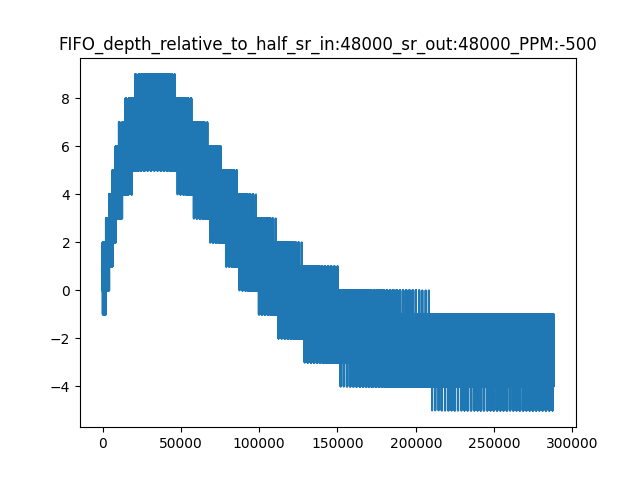
Fig. 12 Peak FIFO excursion at startup for a 500 PPM deviation at 48 kHz output rate.
The size of the FIFO required depends on:
The nominal output rate of the ASRC. This defines how quickly the FIFO fills. Higher rates require a larger FIFO.
The PPM deviation from normal. This defines the maximum deviation of the nominal sample rates and the peak perturbation from half full. The PPM range of the input and output clocks must be added together. For example if a source can vary by up to +500 PPM and the sink can vary by -500 PPM then the system must account for a 1000 PPM worst-case clock rate difference.
The input block size multiplied by the maximum upsample ratio. This defines the “lumpiness” of the real-time FIFO level and needs to be taken account of to fully buffer the block being written. This needs to be supported in both positive and negative PPM cases.
Using the default constants for the loop filter (settings are conservative resulting in convergence time of around four seconds for a large step change in rate) and using the default (and minimum) input block size of four the FIFO should be sized to at least:
FIFO_LEN = (OUTPUT_RATE * PPM / 16000000) + (2 * SRC_N_IN_SAMPLES x SRC_N_OUT_IN_RATIO_MAX)
A sensible choice is to round up FIFO_LEN to the nearest multiple of 2 to ensure it is symmetrical.
A few examples follow for an ASRC input block size of four. Note that the additional latency/group delay added to the system will nominally be half of FIFO depth divided by the output rate:
Input Sample Rate |
Output Sample Rate |
Peak PPM difference |
Minimum FIFO length |
|---|---|---|---|
48000 |
48000 |
250 |
16 |
48000 |
48000 |
500 |
24 |
48000 |
48000 |
1000 |
38 |
48000 |
48000 |
2000 |
68 |
48000 |
96000 |
500 |
46 |
48000 |
192000 |
500 |
96 |
192000 |
48000 |
500 |
20 |
Note
The above settings are for the case when the timestamps are accurately measured. A time stamp relative offset between input and output values may require longer FIFO lengths since this may result in a FIFO nominal fill level away from half full.
Note
Larger input block sizes will require longer FIFO lengths. Scaling the above number by around 1.5 for a block size of eight and 3.0 for a block size of 16 will help reduce the chance of a FIFO overflow or underflow during a frequency step change.
It is recommended to test a system to the maximum PPM tolerance across all supported sample rates to verify the chosen FIFO setting, especially if the goal is to minimise the latency by reducing the FIFO size, otherwise a conservative FIFO size setting may be applied at the cost of additional latency.
Controller settings
The asynchronous FIFO includes a Proportional–integral–derivative (PID) based controller.
The PID constants can be set in two ways:
When used with an ASRC they can be set based on input and output sample rates to a value that stabilises a 375 ppm change in approximately four seconds at 48,000 Hz.
When used in other situations one can provide ones own Kp and Ki values. Both are represented as 32-bit integers, and a typical value for Ki is 422 (at 48 KHz, smaller for higher frequencies), and a typical value for Kp is 28,000,000 (for X kHz to X KHz; higher when the input frequency goes up, smaller when the output frequency goes up).
API
-
enum asynchronous_fifo_get_return_t_
Return code for asynchronous_fifo_consumer_get()
Values:
-
enumerator ASYNCH_FIFO_OK
-
enumerator ASYNCH_FIFO_UNDERFLOW
-
enumerator ASYNCH_FIFO_IN_RESET
-
enumerator ASYNCH_FIFO_OK
-
typedef struct asynchronous_fifo_t_ asynchronous_fifo_t
Data structure that holds the status of an asynchronous FIFO
-
typedef enum asynchronous_fifo_get_return_t_ asynchronous_fifo_get_return_t
Return code for asynchronous_fifo_consumer_get()
- void asynchronous_fifo_init(
- asynchronous_fifo_t *state,
- int channel_count,
- int max_fifo_depth,
Function that must be called to initialise the asynchronous FIFO. The
stateargument should be an int64_t array ofASYNCHRONOUS_FIFO_INT64_ELEMENTSelements that is cast toasynchronous_fifo_t*.That pointer should also be used for all other operations, including operations both the consumer and producer sides.
After initialising, you must initialise the PID by calling one of asynchronous_fifo_init_PID_fs_codes() or asynchronous_fifo_init_PID_raw()
- Parameters:
state – Asynchronous FIFO to be initialised
channel_count – Number of audio channels
max_fifo_depth – Length of the FIFO, delay when stable will be max_fifo_depth/2
- void asynchronous_fifo_init_PID_fs_codes(
- asynchronous_fifo_t *state,
- int fs_input,
- int fs_output,
Function that that initialises the PID of a FIFO. Either this function or asynchronous_fifo_init_PID_raw() should be called. This function uses frequency codes as defined in the ASRC for a quick default setup, the raw function allows full control
- Parameters:
state – Asynchronous FIFO to be initialised
fs_input – Input FS ratio, used to pick appropriate Kp, and Ki. Must be a number less than 6.
fs_output – Input FS ratio, used to pick appropriate Kp, Ki, ideal phase. Must be a number less than 6.
- void asynchronous_fifo_init_PID_raw(
- asynchronous_fifo_t *state,
- int Kp,
- int Ki,
- int ticks_between_samples,
Function that that initialises the PID of a FIFO. Either this function or asynchronous_fifo_init_PID_raw() should be called. This function uses frequency codes as defined in the ASRC for a quick default setup, the raw function allows full control.
This function may be called at any time by the producer in order to alter the PID and midpoint settings. It does not reset the error; one of the asynchronous_fifo_init_reset_producer() or asynchronous_fifo_init_reset_consumer() functions should be called for that.
- Parameters:
state – Asynchronous FIFO to be initialised
Kp – Proportional constant for the FIFO. This gets multiplied by the differential error measured in ticks (typically -2..2) and added to the ratio_error. A typical value is 30,000,000 - 60,000,000.
Ki – Integral constant for the FIFO. This gets multiplied by the phase error measured in ticks (typically -20,000 - 20,000) and added to the ratio_error. A typical value is 200 - 300.
ticks_between_samples – The number of ticks between samples is used to estimate the expected phase error halfway down the FIFO.
-
void asynchronous_fifo_reset_producer(asynchronous_fifo_t *state)
Function that that resets the FIFO from the producer side. Either this function should be called on the producing side, or
asynchronous_fifo_reset_consumershould be called on the consumer side. In both cases the whole FIFO will be reset back- Parameters:
state – Asynchronous FIFO to be initialised
-
void asynchronous_fifo_reset_consumer(asynchronous_fifo_t *state)
Function that that resets the FIFO from the consumer side. Either this function should be called on the consuming side, or asynchronous_fifo_reset_producer() should be called on the producer side. In both cases the whole FIFO will be reset back
- Parameters:
state – Asynchronous FIFO to be initialised
-
void asynchronous_fifo_exit(asynchronous_fifo_t *state)
Function that must be called to deinitalise the asynchronous FIFO
- Parameters:
state – ASRC structure to be de-initialised
- int32_t asynchronous_fifo_producer_put(
- asynchronous_fifo_t *state,
- int32_t *samples,
- int n,
- int32_t timestamp,
Function that provides the next samples to the asynchronous FIFO.
This function and asynchronous_fifo_consumer_get() function both need a timestamp, which is the time that the last sample was input (this function) or output (asynchronous_fifo_consumer_get()). The asynchronous FIFO will hand the samples across from producer to consumer through an elastic queue, and run a PID algorithm to calculate the best way to equalise the input clock relative to the output clock. Therefore, the timestamps have to be measured on either the same clock or two very similar clocks. It is probably fine to use the reference clocks on two tiles, provided the tiles came out of reset at more or less the same time. Using the clocks from two different chips would require the two chips to share an oscillator, and for them to come out of reset simultaneously.
The output is filtered and should be applied directly as a correction factor eg, multiplied into an ASRC ratio, or multiplied into a PLL timing.
- Parameters:
state – ASRC structure to push the sample into
samples – The sample values.
n – The number of samples
timestamp – The number of ticks when this sample was input.
- Returns:
The current estimate of the mismatch of input and output frequencies. This is represented as a 32-bit signed number. Zero means no mismatch, a value less than zero means that the producer is faster than the consumer, a value greater than zero means that the producer is slower than the consumer. The value should be scaled by 2**-32. That is, the current best approximation for consumer_speed/producer_speed is 1 + (return_value * 2**-32)
- asynchronous_fifo_get_return_t asynchronous_fifo_consumer_get(
- asynchronous_fifo_t *state,
- int32_t *samples,
- int32_t timestamp,
Function that gets an output sample from the asynchronous FIFO
Function that implements the consumer interface. Control communication happens through two variables: reset and sample_data_valid. These shall only be set as the last action, as they signify to the production side that the datastructure can now be read on that side.
Note that the samples are filled in regardless of whether the FIFO is operating or not; the consumer will repeatedly get the same sample if the producer fails. The producer side is reset exactly once on reset. If this is a problem then please use the return flag (0 = OK) to handle.
- Parameters:
state – ASRC structure to read a sample out off.
samples – The array where the frame with output samples will be stored.
timestamp – A timestamp taken at the time that the last sample was output. See
asynchronous_fifo_producefor requirements.
- Returns:
The FIFO status and whether the samples are valid or not
-
ASYNCHRONOUS_FIFO_INT64_ELEMENTS(N, C)
macro that calculates the number of int64_t to be allocated for the fifo for a FIFO of N elements and C channels
-
struct asynchronous_fifo_t_
- #include <asynchronous_fifo.h>
Data structure that holds the status of an asynchronous FIFO
- int asrc_timestamp_interpolation(
- int timestamp,
- asrc_ctrl_t *asrc_ctrl,
- int ideal_freq,
Function that interpolates a timestamp for a sample generated by the ASRC. Given a measured timestamp for the sample going into the ASRC, the asrc control structure, and the expected output frequency, this function returns a timestamp for when the last sample was produced by the ASRC.
- Parameters:
timestamp – Value of the reference clock taken when the last sample fed into the ASRC was sampled.
asrc_ctrl – ASRC control block
ideal_freq – Expected base frequency to which the ASRC is operating; eg, 48000 or 44100
Implementation detail
This section details the inner workings of the FIFO and is intended only for advanced users who wish to understand the operation in more detail.
Measurements for the PID
The asynchronous FIFO uses the phase difference as the input for a PID controller. The phase difference is shown in Measurement of the phase difference. It is defined as the time difference between a sample when it entered the queue and left the queue. Unlike traditional phase differences that are measured in radians and where the maximum phase difference is +/- pi , the phase difference is measured as a time difference, and thereby allow the phase to be off by more than half a sample.

Fig. 13 Measurement of the phase difference
In a stable situation, it is desirable that the FIFO is half-full, it follows that the desired phase difference is half the maximum length of the FIFO multiplied by the sample rate. For example, for a FIFO of 10 elements the ideal fill level is 5, and at 48 kHz the ideal phase error is 5 x 2.0833 us = 10.4166 us. If the output is running slightly too fast then sample X will enter the FIFO just after X-N/2 leaves the FIFO; if the output is running slightly too slow than sample X will enter the FIFO just before X-N/2 leaves the FIFO.
The phase-error is defined as the difference between the ideal phase-difference and the measured phase difference. Say that the queue has filled up badly and stores 9 items, then the phase difference will account for the 4 extra items in the FIFO, causing a phase difference 18.75 us rather than the desired 10.4166 us, producing a phase error of between 8.33 us. The phase difference is notionally a continuous value (a time stamp) in practice it is measured with the reference clock which has a 10 ns granularity. However, that is of far higher granularity than whole samples (2083 times better at a 48 KHz sample rate)
It is worth noting that the phase difference itself is an integral value; it is the number of samples since the beginning of time that the ASRC is out by. The goal of the rate converter is to make the phase difference stable (ie, it does not move between subsequent samples), and zero (ie, the FIFO is exactly mid level). Hence, the differential of the phase error can be seen as a proportional error, and the phase error itself as an integral error.
Implementation of asynchronicity
The FIFO straddles two threads; this is essential as the two threads operate on different rates. Hence, the FIFO is a shared-memory element between those two threads. A read-pointer (managed by the consuming thread) and a write-pointer (managed by the producing thread) are maintained independently. The read-pointer and write-pointer are normally N/2 elements apart.
During normal operation the Incoming and outgoing traffic are rate-matched, and the read-pointer and write-pointer will be on opposite ends of the circular buffer.
There are three situations where operation may be abnormal:
Where the consumer is no longer consuming samples
Where the producer is no longer producing samples
Where a larger than expected change in the sample rates has caused the loop filter to require more than N/2 spaces away from the mid-point.
Detecting these cases requires the calculation of the modulo difference between the write-pointer and read-pointer; if that difference is close to zero the FIFO is about to underflow; if it is close to N the FIFO is about to overflow. The notion “close to” is used since the read- and write-pointer are updated independently by different threads, so the pointer may be one less than anticipated, and an update may be missed (i.e. a race condition). Underflow is detected by the thread on the output side, overflow is detected by the thread on the input side. Differentiating overflow/underflow from too large a change in the sample rate may be hard and not necessary if they are all treated in the same way.
The employed method is to use two flags; RESET and DO_NOT_PRODUCE
that are owned by the consumer and producer sides respectively.
The
RESETflag is set by the consumer if it spots an underflow condition. OnceRESETis set, the consumer will no longer advance the FIFO, return the same sample on each call, and wait forRESETto clear. Only the consumer may setRESET, only the producer may clearRESET.The
DO_NOT_PRODUCEflag is set by the producer if it spots on overflow condition. Once set, the producer will no longer advance the FIFO, and wait for the consumer to set theRESETflag once it has come to an underflow (which must happen as the producer has stopped producing), at which point a third action is met.If the producer spots
RESETbeing high, it resets the FIFO state except for the read-pointer; it leaves that as it is maintained by the consumer. Instead, it sets the write pointer to be at the other side of the buffer. Once the state is reset it will clearDO_NOT_PRODUCEand finallyRESET, whereupon all should start running again.
Communication and reset protocol summary
In the thread on the producer side a put() operation performs the following:
If the
RESETflag is set:
Set the write-pointer to half-way from the read-pointer
Set
fs_ratioto 1Clear the phase error and reset all other PID state.
Clear the
DO_NOT_PRODUCEflagClear the
RESETflag (this is the last step, unlocking the consumer when it is safe to do so)else if there is no room left in the FIFO to store all samples:
Set the
DO_NOT_PRODUCEflagelse if the
DO_NOT_PRODUCEflag is not set:
Copy
Nframes into the FIFOIncrease the write-pointer
Obtain a timestamp that was queued by the consumer
Calculate the phase-error and the difference with the previous phase error
Update the PID using the difference as the proportional error and the phase-error as the integral error.
In the thread on the consumer side a get() operation performs the following:
Copy the sample at the read-pointer into the buffer provided by the consumer
If the
RESETflag is clear and there is at least one sample in the FIFO:
Record the timestamp in the time-stamp queue
Increase the read-pointer.
else if the
RESETflag is clear:
Set the
RESETflag.