lib_spdif: S/PDIF library
Introduction
S/PDIF (Sony/Philips Digital Interface) is a standard for transmitting digital audio signals over relatively short distances between devices. It was developed by Sony and Philips and is used to carry high-quality digital audio without the need for analog conversion, maintaining the integrity of the audio signal.
S/PDIF can carry two channels of uncompressed PCM (Pulse Code Modulation) audio or over Optical (TOSLINK) or Coaxial transmission mediums.
lib_spdif provides software defined S/PDIF implementation that allows transmission and reception
of S/PDIF data via xcore ports.
Using lib_spdif
lib_spdif is intended to be used with the XCommon CMake
, the XMOS application build and dependency management system.
To use this library, include lib_spdif in the application’s APP_DEPENDENT_MODULES list, for example:
set(APP_DEPENDENT_MODULES "lib_spdif")
Applications should then include the spdif.h header file.
External signal description
The library implements the S/PDIF (Sony/Philips Digital Interface Format) protocol for transporting uncompressed stereo PCM data of up to 24bits.
Note
The S/PDIF connections shown in the diagrams below are digital representations of S/PDIF and not an actual signal suitable for external devices (which is 0.5V pk-pk etc). External circuitry is required to interface with the chosen medium (optical or electrical).
Connecting to the xcore as transmitter
The precise transmission frequencies supported depend on the availability of an external clock (e.g. a PLL or a crystal oscillator) that runs at a frequency of channels * sampleRate * 64 or a power-of-2 multiple. For example, for 2 channels at 192 KHz the external clock has to run at a frequency of 24.576 MHz. This same frequency also supports 2 channels at 48 KHz (which requires a minimum frequency of 6.144 MHz). If both 44,1 and 48 KHz frequencies are to be supported, both a 24.576 MHz and a 22.579 MHz master clock is required.
When using an xcore.ai based device these frequencies can be generated by the on-chip application/secondary PLL.
The connection of an S/PDIF transmit line to the xcore is shown in Connecting S/PDIF transmit.
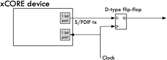
Fig. 1 Connecting S/PDIF transmit
The output signal will contain jitter at the level of +/-1 core clock (<2ns for a 500 MHz xcore) this is typically inconsequential but if lower jitter levels are desired the signal can be re-clocked by the external master clock to reduce the jitter to that of the external master clock. A simple D-type flip flop can be used for this purpose.
The incoming clock signal is used to drive an internal clock and can be shared with other software functions using the same master clock (e.g. ADAT transmit or I2S).
Note
The transmit stream user bits are set to 0. The validity bits are set to 0 (i.e. valid).
Connecting to the xcore as receiver
The receiver can receive stereo PCM signals up to 192 KHz.
The connection of an S/PDIF receiver line to the xCORE is shown in Connecting S/PDIF receiver.
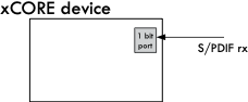
Fig. 2 Connecting S/PDIF receiver
Note
Only a single wire is connected - the clock is recovered from the incoming data stream.
Usage
All S/PDIF functions can be accessed via the spdif.h header:
#include <spdif.h>
lib_spdif should also be added to the APP_DEPENDENT_MODULES application XCommon-CMake
CMakeLists.txt file.
Note
The receiver and transmitter tasks each require a minimum of 62.5MHz to operate correctly.
S/PDIF transmitter
S/PDIF components are instantiated as parallel tasks that run in a
par statement. The application can connect via a channel
connection.

Fig. 3 S/PDIF transmit task diagram
For example, the following code instantiates an S/PDIF transmitter component and connects to it:
on tile[1]: out buffered    port:32 p_spdif_tx      = XS1_PORT_1A;
on tile[1]: in              port    p_mclk_in       = XS1_PORT_1D;
on tile[1]: clock                   clk_audio       = XS1_CLKBLK_1;
int main(void) {

    chan c_spdif;
    par
    {
        on tile[0]: {
            board_setup();
            while(1) {};
        }
        on tile[1]: {
            spdif_tx_port_config(p_spdif_tx, clk_audio, p_mclk_in, 7);
            start_clock(clk_audio);
            spdif_tx(p_spdif_tx, c_spdif);
        }
        on tile[1]: generate_samples(c_spdif);
    }
    return 0;
} // end
The helper function spdif_tx_port_config() clocks the clock-block from the master clock
port and, in turn, clocks the S/PDIF transmit port from this clock-block.
The application can communicate with the components via API functions that take the channel end as arguments e.g.:
void generate_samples(chanend c) {
    int i = 0;
    spdif_tx_reconfigure_sample_rate(c,
                                     SAMPLE_FREQUENCY_HZ,
                                     MCLK_FREQUENCY_48, WORD_LENGTH);
    while(1) {
       // Generate a sine wave
       int sample = sine_table[i];
       i = (i + 1) % SINE_TABLE_SIZE;
       spdif_tx_output(c, sample, sample);
    }
}
Configuring the underlying clock
When using the transmit component, the internal clock needs to be configured to run off the incoming signal e.g.:
spdif_tx_port_config(p_spdif_tx, clk_audio, p_mclk_in, 7);
This function needs to be called before the spdif_tx() function in
the programs par statement.
In this function the configure_clock_src() is used configure a clock to run off an
incoming port - see the XMOS Programming Guide for more information.
The last parameter is used with the set_clock_fall_delay() function to configure an
internal delay from the incoming clock signal to the internal clock’s falling edge.
This is done to allow for the correct alignment of outgoing data with
the master clock at the external D-type flip-flop.
Note, the delay value shown above is a typical example and may need to be tuned for the specific hardware being used.
S/PDIF receiver
S/PDIF components are instantiated as parallel tasks that run in a
par statement. The application can connect via a channel
connection.
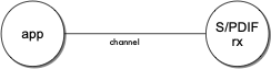
Fig. 4 S/PDIF receiver task diagram
For example, the following code instantiates an S/PDIF receiver component and connects to it:
on tile[0]: in              port    p_coax_rx       = XS1_PORT_1N;
on tile[0]:                 clock   audio_clk       = XS1_CLKBLK_1;
int main(void)
{
    streaming chan c;
    par {
        on tile[0]: {
            board_setup();
            spdif_rx(c, p_coax_rx, audio_clk, 96000);
        }
        on tile[0]: handle_samples(c);
    }
    return 0;
} // end
The application can communicate with the components via API functions that take the channel end as arguments e.g.:
void handle_samples(streaming chanend c)
{
    int32_t sample;
    size_t index;
    int32_t left_count = 0;
    int32_t right_count = 0;

    while(1)
    {
        select
        {
            case spdif_rx_sample(c, sample, index):
            // sample contains the 24bit data
            // You can process the audio data here
            if (index == 0)
                left_count++;
            else
                right_count++;
            break;
        }

        int32_t total = left_count + right_count;

        if (total % 10000 == 0)
        {
            debug_printf("Received %u left samples and %u right samples\n",
                   left_count,
                   right_count);
        }
    }
}
Note that a program can react to incoming samples using a
select statement. More information on using par and select
statements can be found in the XMOS Programming Guide.
Each 32-bit word received from the receive component via the channel has the following format:
Bit(s) |
Field |
|---|---|
3:0 |
Preamble |
7:4 |
Auxiliary data |
27:8 |
Audio sample |
28 |
Validity |
29 |
User |
30 |
Control |
31 |
Parity |
Note
The four auxilary data bits are typically used to extend the audio sample from 20 to 24 bits.
The spdif_rx_sample() helper function strips away all fields other than the Audio Sample and Auxiliary data and returns
this audio sample data in the upper 24 bits of the sample variable.
Should other fields be desired - for parity checking, for instance, regular channel communication syntax can be used. For example:
void my_application(streaming chanend c)
{
   int32_t sample;
   size_t count = 0;

   while(1)
   {
     c :> spdif_data;

     // Check parity
     int parity_error = spdif_rx_check_parity(spdif_data);

     if (parity_error == 0)
       count++;
   }
   ...
API
Creating an S/PDIF transmitter instance
- void spdif_tx_port_config(
- out_buffered_port_32_t p,
- clock clk,
- in_port_t p_mclk,
- unsigned delay,
S/PDIF transmit configure port function
This function configures a port to be used by the S/PDIF transmit function.
This function takes a delay for the clock that is to be passed into the S/PDIF transmitter component. It sets the clock such that output data is slightly delayed. This will work if I2S is clocked off the same clock but ensures S/PDIF functions correctly.
- Parameters:
p – the port that the S/PDIF component will use
clk – the clock that the S/PDIF component will use
p_mclk – The clock connected to the master clock frequency. Usually this should be configured to be driven by an incoming master system clock.
delay – delay to uses to sync the SPDIF signal at the external flip-flop
-
void spdif_tx(out_buffered_port_32_t p_spdif, chanend c)
S/PDIF transmit function.
This function provides an S/PDIF transmit component. It is capable of 44100, 48000, 88200, 96000, and 192000 Hz sample rates and 16, 20 or 24 bits of sample word lengths.
The sample rate or word length can be dynamically changed during the operation of the component. Note that the first API call to this component should be to reconfigure the sample rate and the word length (using the spdif_tx_reconfigure_sample_rate() function).
- Parameters:
p_spdif – The output port to transmit to
c – chanend to connect to the application
S/PDIF transmitter API
-
SPDIF_TX_ENABLE_PRO_CHANNEL_STATUS
Selects whether the S/PDIF transmitter builds a Professional (AES3) channel status block or a Consumer (S/PDIF) channel status block.
Building consumer block by default. Can be overriden by defining SPDIF_TX_ENABLE_PRO_CHANNEL_STATUS (1) or passing a compiler build flag -DSPDIF_TX_ENABLE_PRO_CHANNEL_STATUS=1 to build professional channel status block.
- void spdif_tx_reconfigure_sample_rate(
- chanend c_spdif_tx,
- unsigned sample_frequency,
- unsigned master_clock_frequency,
- unsigned word_length,
Reconfigure the S/PDIF tx component to a new sample rate or sample word length.
This function instructs the S/PDIF transmitter component to change sample rate or the sample word length.
- Parameters:
c_spdif_tx – chanend connected to the S/PDIF transmitter
sample_frequency – The required new sample frequency in Hz.
master_clock_frequency – The master_clock_frequency that the S/PDIF transmitter is using
word_length – word length in bits of the transmitted samples. Supported values - 16, 20 or 24bits
-
void spdif_tx_output(chanend c_spdif_tx, unsigned lsample, unsigned rsample)
Output a sample pair to the S/PDIF transmitter component.
This function will output a left channel and right channel sample to the S/PDIF transmitter.
- Parameters:
c_spdif_tx – chanend connected to the S/PDIF transmitter
lsample – left sample to transmit
rsample – right sample to transmit
-
void spdif_tx_shutdown(chanend c)
Shutdown the S/PDIF transmitter component.
This function shuts down the SPDIF Tx component causing the call to spdif_tx() to return.
- Parameters:
c – chanend connected to the S/PDIF transmitter component
Creating an S/PDIF receiver instance
- void spdif_rx(
- streaming_chanend_t c,
- in_port_t p,
- clock clk,
- unsigned sample_freq_estimate,
S/PDIF receive function.
This function provides an S/PDIF receiver component. It is capable of receiving 44100, 48000, 88200, 96000, 176400 and 192000 Hz sample rates.
The receiver will modifiy the divider of the clock-block to lock to the incoming sample rate.
- Parameters:
c – Channel to connect to the application.
p – S/PDIF input port.
clk – A clock block used internally to clock data.
sample_freq_estimate – The initial expected sample rate (in Hz).
S/PDIF receiver API
- void spdif_rx_sample(
- streaming_chanend_t c,
- REFERENCE_PARAM(int32_t, sample),
- REFERENCE_PARAM(size_t, index),
Receive a sample from the S/PDIF component.
This function receives a sample from the S/PDIF component. It is a “select handler” so can be used within a select e.g.
 int32_t sample;
 size_t index;
 select {
   case spdif_rx_sample(c, sample, index):
        // use sample and index here...
        ...
        break;
 ...
The case in this select will fire when the S/PDIF component has data ready.
- Parameters:
c – chanend connected to the S/PDIF receiver component
sample – This reference parameter gets set with the incoming sample data
index – This is the index of the same in the current frame (i.e. 0 for left channel and 1 for right channel).
-
void spdif_rx_shutdown(streaming_chanend_t c)
Shutdown the S/PDIF receiver component.
This function shuts down the SPDIF RX component causing the call to spdif_rx() to return.
- Parameters:
c – chanend connected to the S/PDIF receiver component
-
static inline int spdif_rx_check_parity(unsigned sample)
Checks the parity of a received S/PDIF sample
- Parameters:
sample – Received sample to be checked
- Returns:
Non-zero for error parity, otherwise 0